Home › Forum › Ask A Member › Caille Neptune gear case rebuilt
- This topic has 8 replies, 2 voices, and was last updated 3 years, 5 months ago by
 Buccaneer.
-
AuthorPosts
-
November 16, 2020 at 1:40 pm #220981
I was finally able to get the drive shaft removed from the gear case.
While the two gears are useable, worn, but no missing teeth at least,
the prop shaft and the parts it resides in, were very worn.
The thrust adjustment plug in the front of the case was previously
repaired by someone using solder, trying to make the hole smaller.
I bored it out a ways until it’s round again, and this piece will need
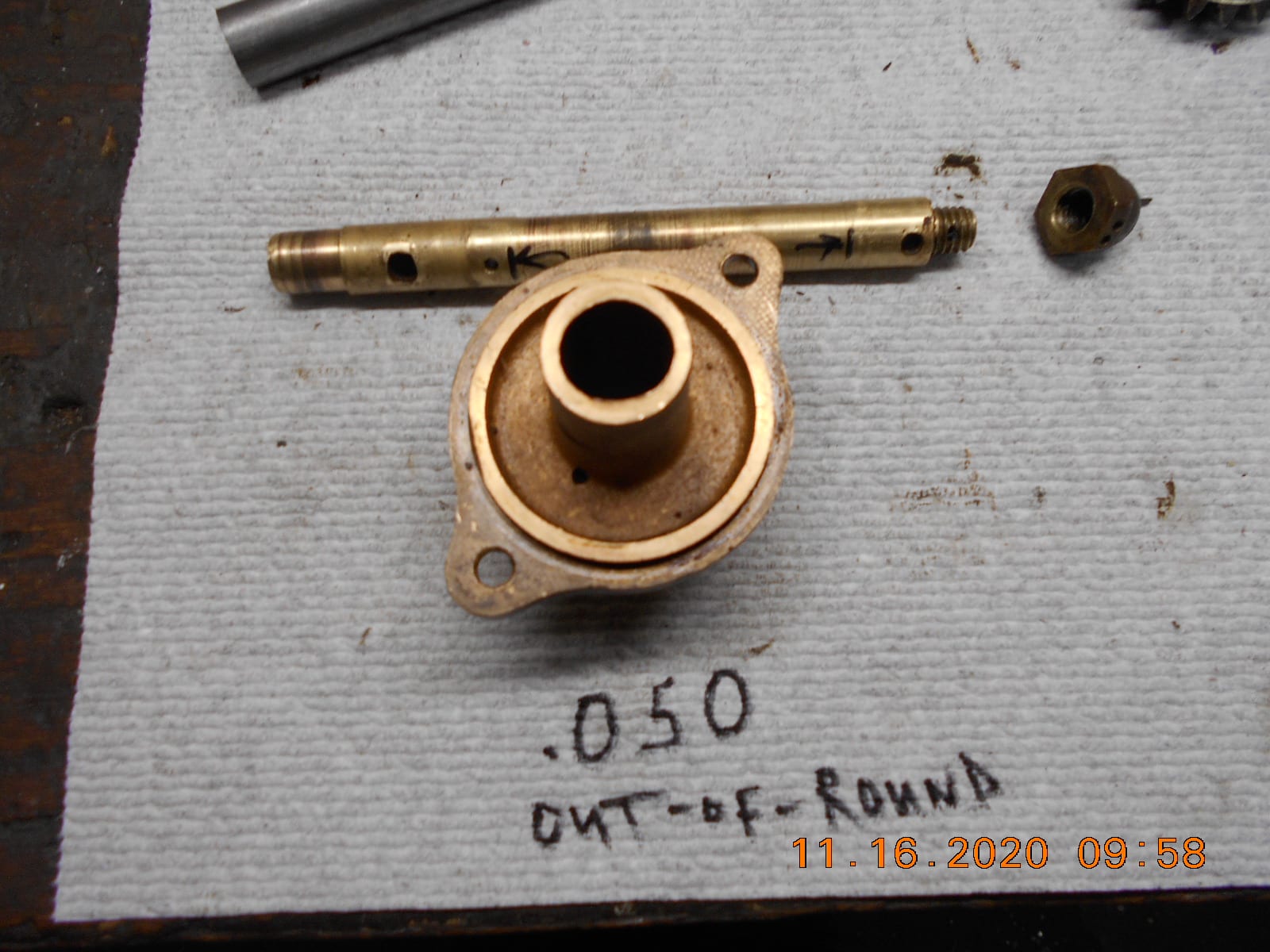
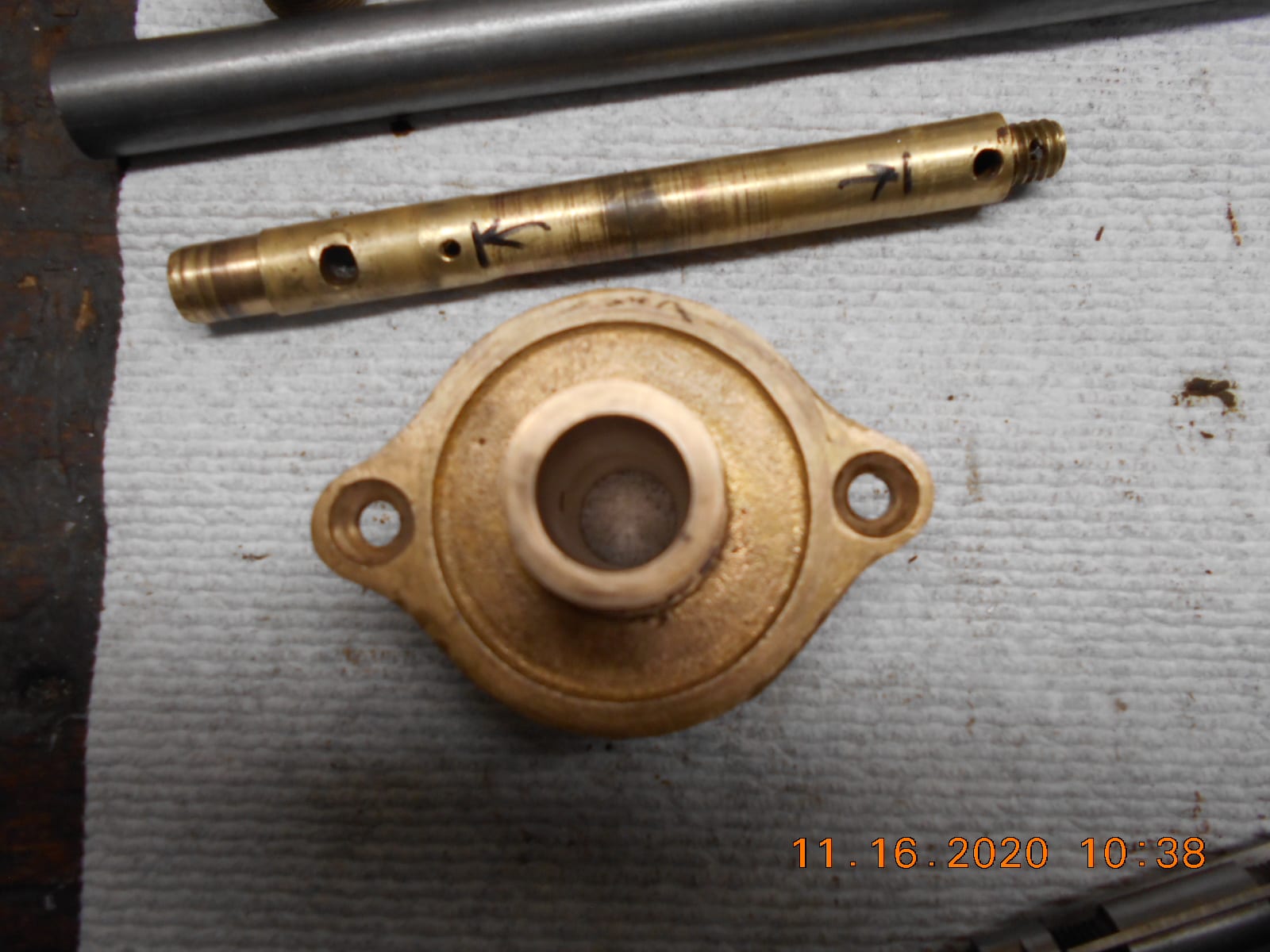
a bushing, once I decide on the new prop shaft size.The gear case cover, which is the main prop shaft support / carrier bearing, was
worn out-of-round on the inboard end about .050, and sloppy, but less so
on the outboard end.
I bored this out the minimum to make it “round” again, and will try to make
a new prop shaft to fit the carrier’s new bore.The original prop shaft is brass, and worn considerable where it rode in the carrier.
I was planning on making (or trying to!) the new prop shaft out of 3/4″ steel round stock,
as that’s what I have. The drive shaft is steel. Any reason a steel prop shaft
wouldn’t be advisable, other that it rusting away eventually?
If this project does run, it’s not likely to get a lot of use.
I thought about making the prop shaft back to original specs, but then I would
have to bore out the carrier larger for bushings, and I’m afraid that it might
weaken the carrier / gear case cover, and “break” under load.How would you guys rebuilt this gear case?
Thoughts appreciated.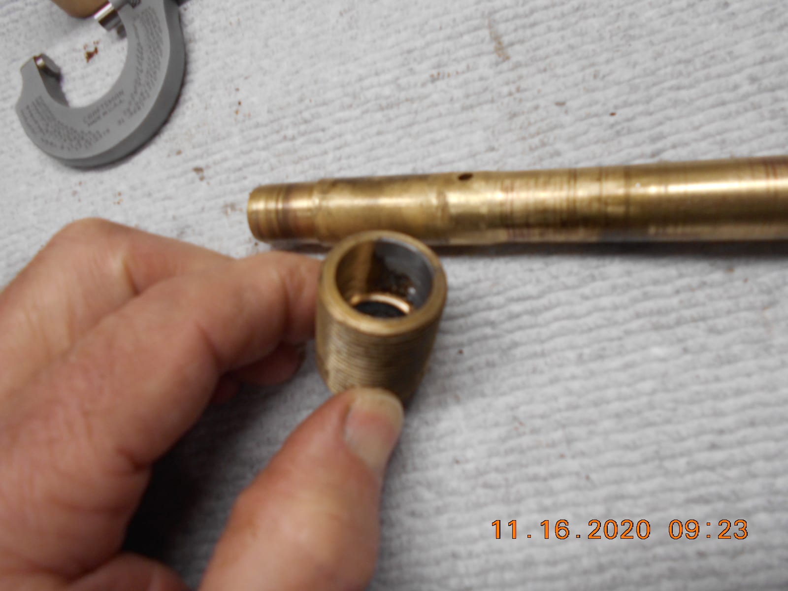
Prepare to be boarded!
November 16, 2020 at 7:31 pm #221030The original propshaft size is 0.625″ (5/8ths) and I recommend that you make a new one to that dimension and bush the supporting parts in the lower unit accordingly.
I’ve done enough rowboat motor lower units to say that when done correctly, you can rebush the original parts and not have to worry about weakening the original castings.
The exception may be the lash adjustment screw in the nose, depending on how worn it is and if its been carved out already. I have had them so worn out that the threaded part had holes in it from the front end of the propshaft chewing through it. In those cases, I opt to machine a whole new adjuster screw and insert a bushing right from the get go. Alternative is that you can machine a new adjuster screw out of solid 660 bearing bronze and not bother with a bushing. And don’t forget about the little round piece of lignum vitae that is supposed to be up in the front of the adjuster screw and acts as a thrust bearing.
My procedure for repairing the rear lower unit cover is as follows;
To bore out the rear bearing carrier (aka rear cover), use the chuck to grab it around the diameter that fits inside your gear housing and indicate to get it as centred as possible. There isn’t a lot of shoulder there to hold onto, but its enough because you are going to take your time and only take light cuts when you bore it out.This gives you the best chance to bore it out so that the hole you carve is concentric with the locator ring on that rear cover. They use 5/8ths diameter shafts so bore the hole out to 0.750″, then machine a bushing that allows for a 0.001″ press fit into the rear cover. You want about 0.002″ clearance between the new bushing and the new propshaft, but no more than that.
Make the propshaft to original specs, and rework the other parts to make them fit it. I recommend trying to avoid making a stepped driveshaft to accommodate other worn or oversize bushings if at all possible.
Disclaimer – Since its not me doing the work, I won’t guarantee your results, and accept no liability for any wayward results.
Hope this helps.
Best,
PM T2November 16, 2020 at 10:08 pm #221034Thanks PM T2 for sharing you Caille experience.
I know you suggest machining the shaft to original specs, but do
you have anything against using steel round stock instead of brass
to do so?I’d like to make a new threaded adjustment plug that fits the prop shaft
correctly, but after my failed attempt of making a tool to go into said
threaded hole, I have to figure out what’s wrong with my thread profile.
Just ordered a wire gauge set for checking thread depth, seeing
how I don’t have a 15/16 x 18 tpi nut to check “fit” before I lob off
the part from the lathe. May be the nose profile of my threading inserts…..
don’t know…… still learning as I go.
Regarding the lignum vitae, I’m not aware of any Guaiacum tree’s around,
so may have to use Delron.
Thanks!Prepare to be boarded!
November 17, 2020 at 12:39 am #221038There is no real disadvantage to using steel bar for a new propshaft other than you know its going to rust wherever its not buried in grease.
I used to make them out of 12L14 steel because it machines so easily, but it’s far from rust proof. You could use either cold or hot rolled steel bar if you want. I have switched to 303 stainless for most of my propshafts now. Its good and strong, rust-proof, and the easiest grade of SS for me to machine.
Brass is the easiest to machine, but plain 360 yellow brass is a bit too soft for propshafts, but its fine for a motor that you know isn’t going to run very much.
FWIW I have a bin where I keep the brass driveshafts that I sometimes find in Evinrude rowboat motors. They almost always have a twist in them, so I make new ones out of stainless….. but they are good for making brass drifts out of, as well as teaching other members about some of the weird things that happen with rowboat motors.
Thrust bearing – You could use Delrin, I guess….. or you can use a piece of hardwood dowel. The lignum vitae is just a real dense type of wood, so you could use your imagination for some sort of substitute. If I get desperate I just cut another piece of bearing bronze down and shove it down to the end. I sometimes see little packets of those wood thrust bearings at the club events like Tomahawk. I always grab them if I do run into them. Most people don’t know what they’re for, but most likely wouldn’t have a use for them if they did. I spose I could hand them out and say “here’s a piece of black licorice, you’ll love it” and sit back and watch what happens when they try to suck on it……..
Hope it helps.
Best,
PM T2November 17, 2020 at 8:32 am #221040PM T2, thanks again, for the metalurgical & plug makin lessons.
I forgot to ask about the driveshaft bushing. It’s not in great shape
either, but not near as sloppy as the prop shaft was.I’m not 100% sure there’s actually a bushing down that driveshaft tube,
or if the hole was just bored in the casting inside the tube?I made a stepped bushing puller plate and tried to pull the bushing
out with the ready-rod method, but nothing budged. I did not
attempt to use heat. If there is a bushing in there, it’s walls would seem
to be 1/8″ or less.
What’s your experience in this area?
Thanks.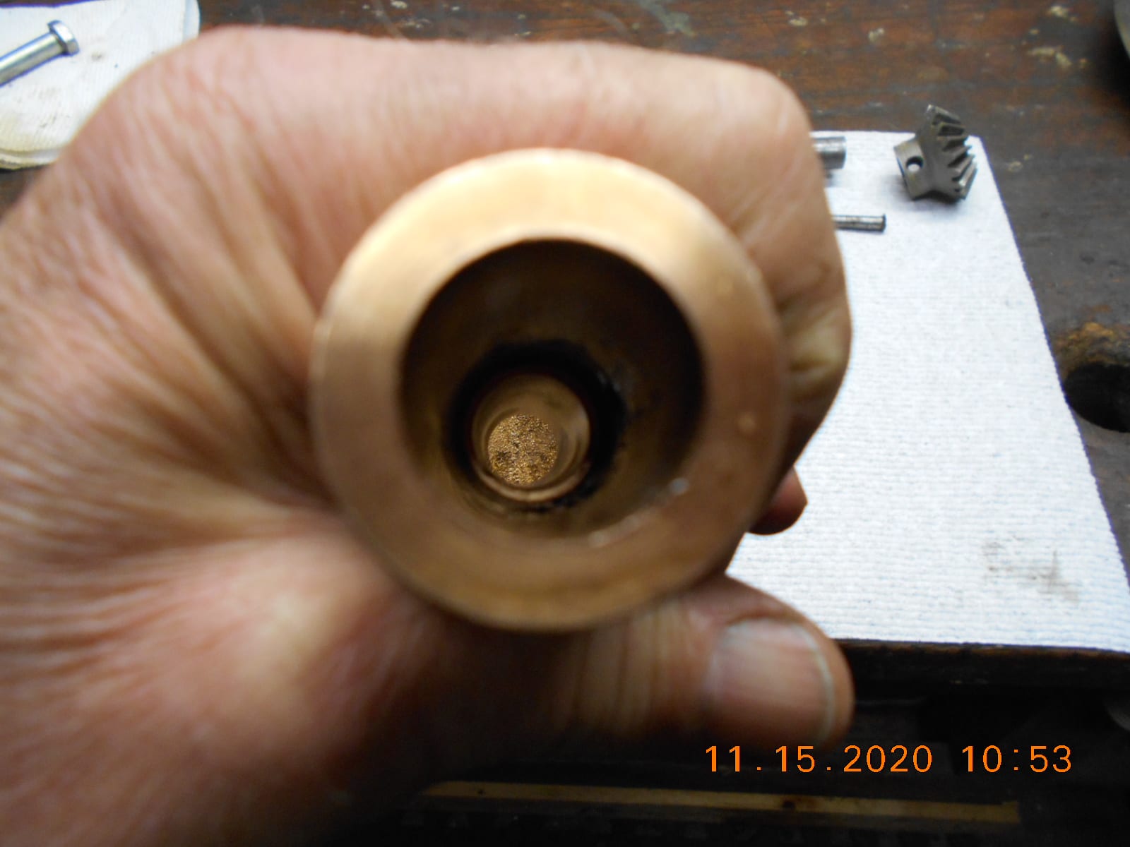
Prepare to be boarded!
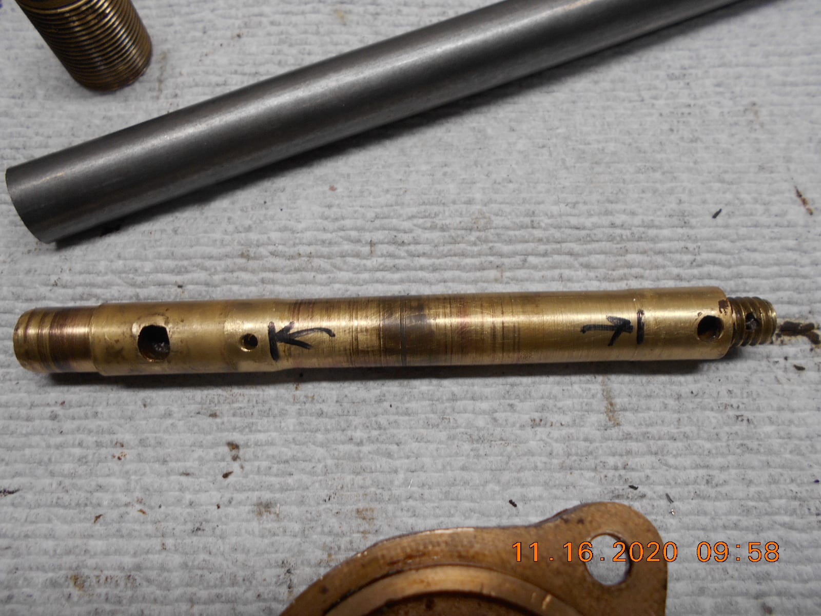
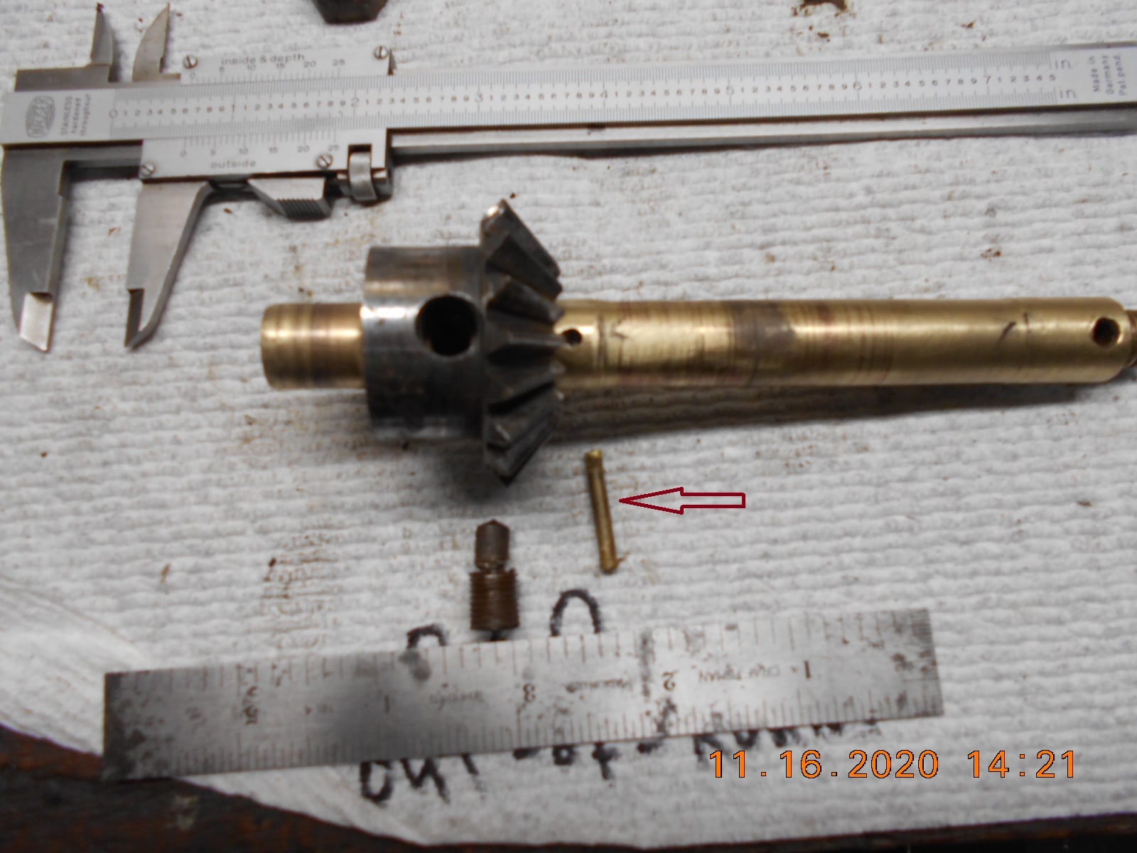
November 17, 2020 at 6:57 pm #221081I’m not sure what this small brass pin is even for. Anyone know?
The gear / cam lobe is pinned to the prop shaft elsewise, and the
pin doesn’t contact the prop shaft bearing carrier ahead of the pin.Just pondering when I make the new prop shaft if I even need this pin?
Prepare to be boarded!
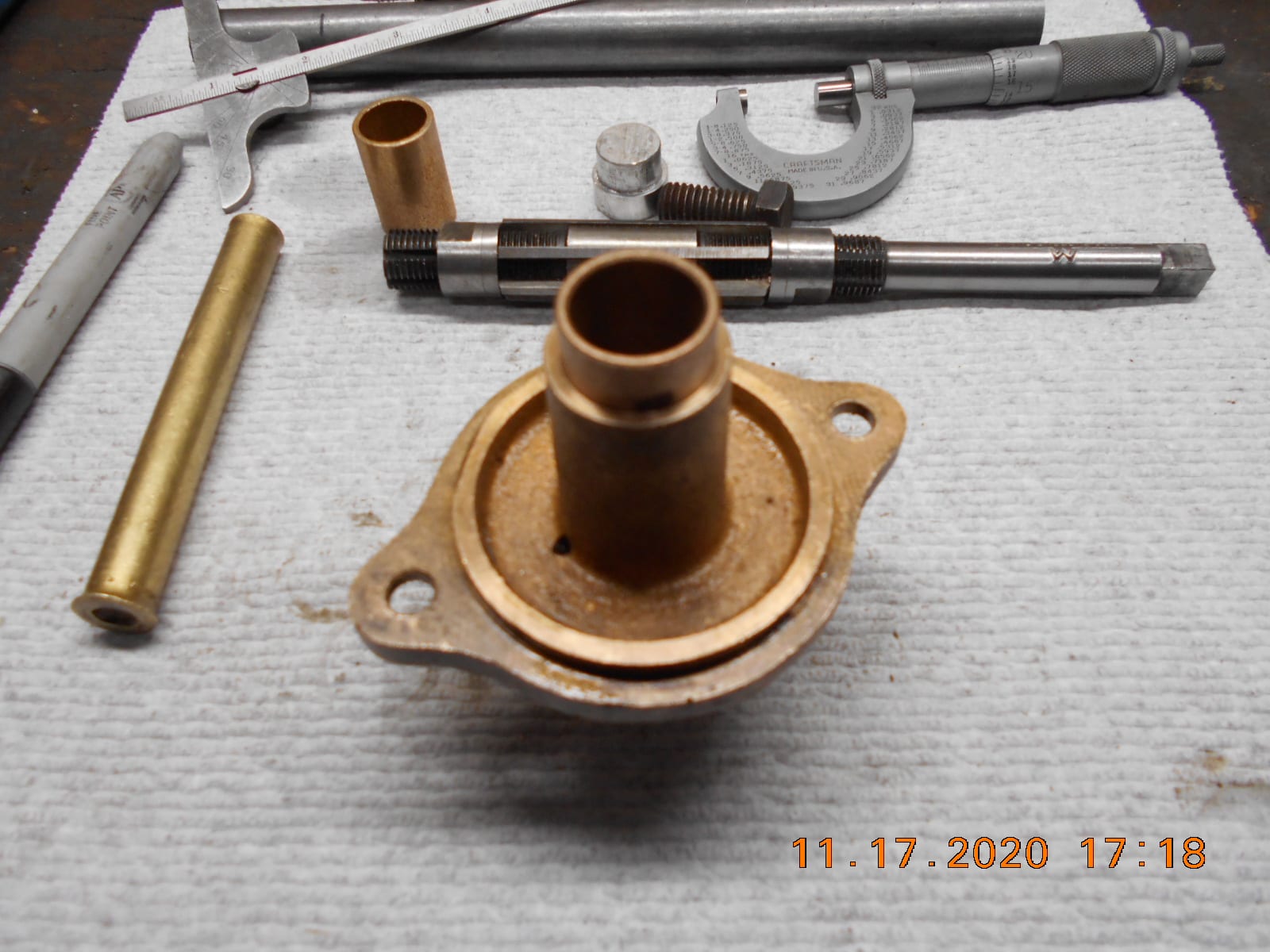
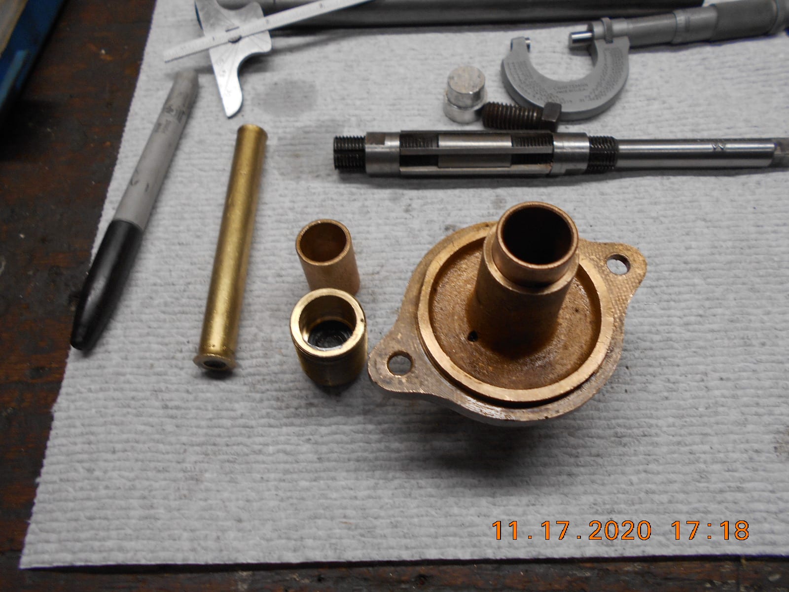
November 17, 2020 at 7:16 pm #221085I bored out the gear case cover in the lathe per PM T2’s thoughts,
and installed 3/4″ OD x 5/8″ ID bronze bushings. I cheated, and purchased
some 1-1/8″ bushings from the local hardware and press them in the bore.
Not sure of the quality or the proper use of said purchased bushings, but
the should last longer than I need them to.
I pressed in three bushings, but need to cut off the extra bushing length tomorrow,
and drill the lubrication hole thru the middle bushing.I “believe” that the gear case cover bore (that I put the bushings in) had
lubrication grooving in it, but I can’t swear to it now.
Perhaps just a straight groove, but possibly spiral.
I was thinking of doing a straight lubrication groove in the bushings using
a boring tool in the lathe, starting in the center drilled hole, and dragging
the boring tool (with the lathe off) to dig the groove.
Anyone have a better idea?I still have to finish boring out the threaded plug in the front of the gear case
for a bushing.
Thanks.
Prepare to be boarded!
November 18, 2020 at 10:53 pm #221181Regarding the driveshaft support bearing – typically the section of the lower unit that supports the lower end of the driveshaft was not bushed from the factory. Usually the casting is bored out to finished size. When the driveshaft bore gets worn out, it is almost always a nuisance to repair if you don’t have a jig for it, or a way to hold it in your lathe. My usual method to fix this part is to clamp the gear housing to an angle plate in a milling machine and bore it out. The skeg makes it a pain in the butt to get it lined up and indicated, but with enough parallels and clamps in the tool kit, I manage to get thru it without burning up the air around me with words that aren’t fit for listening to. This is one area where I will admit to having bowed to the Spirit Of The Unholy Shortcut, and machined a stepped shaft to work around a worn out bearing bore after I reamed the hole out to the point that it was more or less round again. That was in the days when I either had no machining equipment to work with, or lacked the prerequisite level of knowledge to know how to do it better. But it is a shortcut that can get you by, especially if you can’t hold the work in a lathe chuck or fixture, and a milling machine isn’t available.
Regarding the choice of bearing – If its off the shelf, its likely an oilite bronze bushing, or similar material. They will do fine in the short term, and if you’re only planning on getting a few hours of fun out of the motor before it retires, you will get your moneys worth out of them. Plus, you can always press them out later and replace with SAE 660 bronze if you want.
Oil groove – your method would work. My neanderthal method involves first cutting (or broaching, to put it more accurately) a straight groove in the bushing with a boring bar. Obviously you don’t want to go all the way through the bushing, I aim for about making the groove 80% of the length of the bushing. When I get the groove to the depth I want, I just put a bit more tension on the boring bar and put the lathe in back gears at the lowest RPM, then rapidly withdraw the tool as soon as the lathe is turned on. I get a spiral cut groove that is as deep as the one I just broached. The sound the tool makes as your withdraw it from the work will cause all the other tools you own want to run for the hills lest they be subjected to similar abuse…. I did say it was a brutal way to do it, but it works. I’d like to build an apparatus that uses arms attached to the chuck to move the carriage back and forth in such a manner that you can make those nice figure 8 oiling grooves, but I haven’t gotten around to that yet.
Hope this helps.
Best,
PM T2-
This reply was modified 3 years, 5 months ago by
 pm-t2.
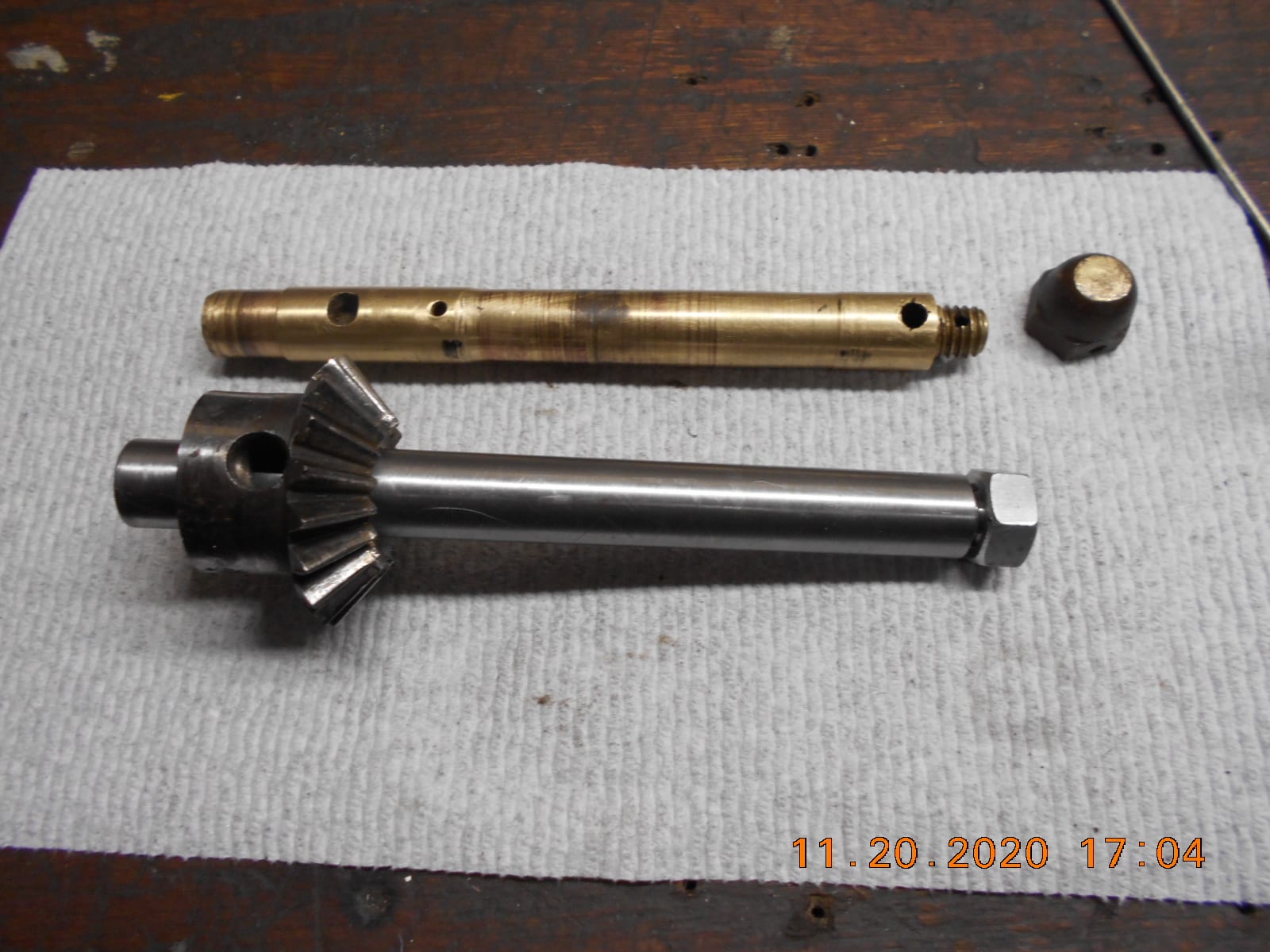
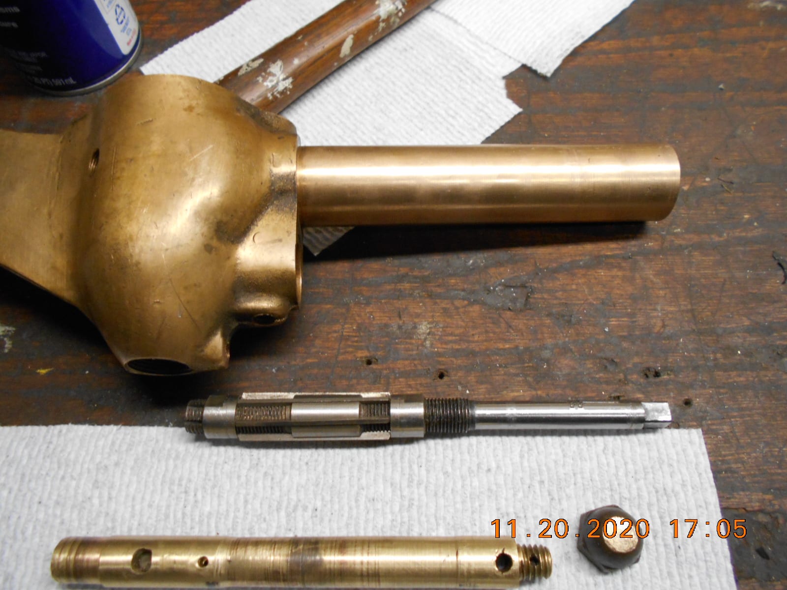
November 20, 2020 at 7:07 pm #221287I got my lathe operational again, so other than drilling the cross holes in the shaft, the machining is done.
I still haven’t figured out what the brass pin between the gear and bearing carrier is for….. sling grease around?
Have not decided what to do about the sloppy driveshaft bore yet. No milling machine, and it’s not feasible to
bore out on my lathe to install bushings or oversize driveshaft. An oversize driveshaft build might be problematic
as well, as there’s a very long keyway in the shaft that engages in the coupler that I’d be ill equip to reproduce….
any brilliant ideas? My original driveshaft is steel, and it’s not too bad of shape…… most
of the wear is in the brass bore. My adjustable reamer might take a month of Sundays to ream out the bore
an 1/8″ for installing bushings, but a possibility perhaps.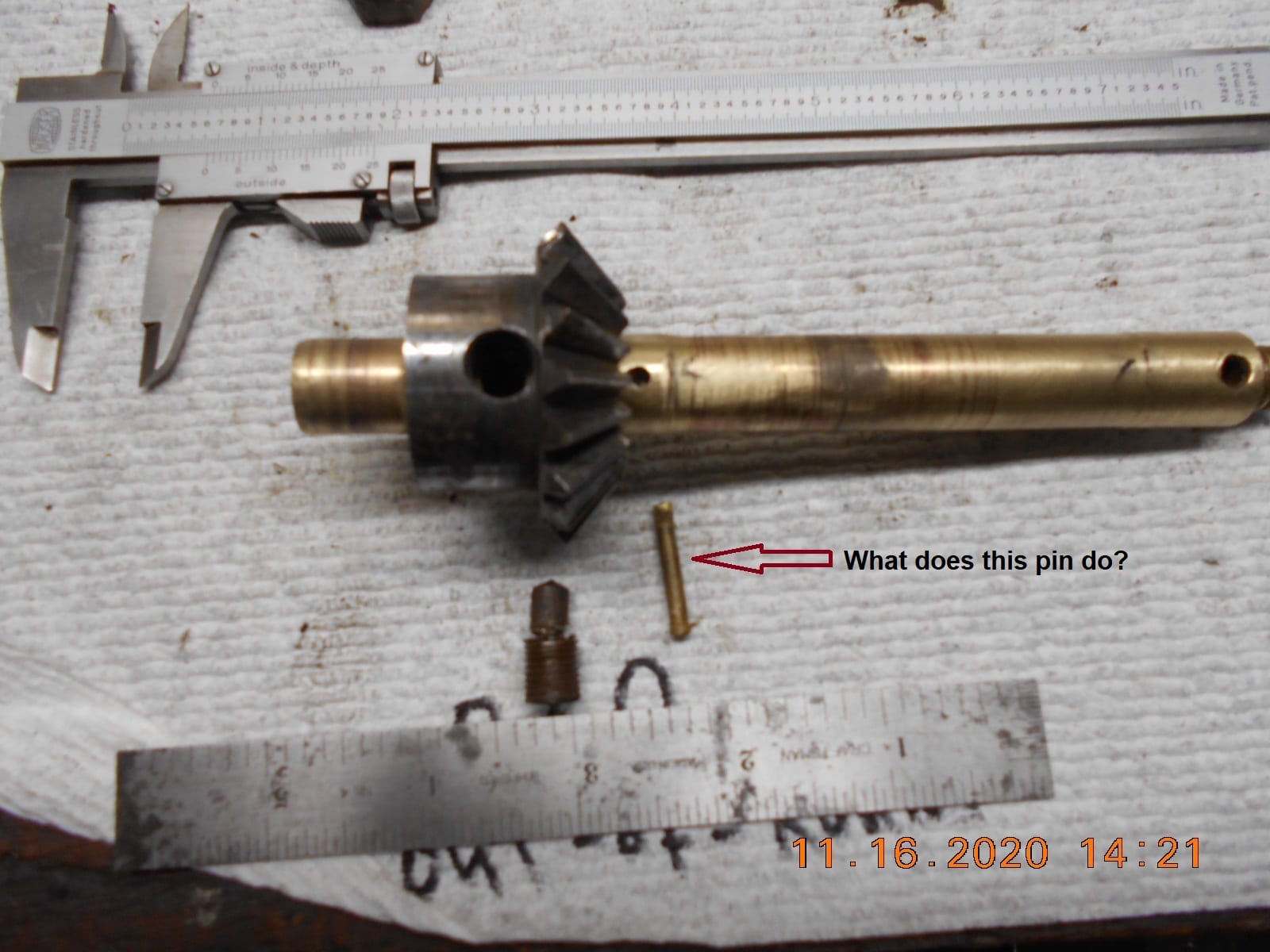
Prepare to be boarded!
-
This reply was modified 3 years, 5 months ago by
-
AuthorPosts
- You must be logged in to reply to this topic.