Home › Forum › Ask A Member › 1914 Evinrude Rowboat Motor
- This topic has 3 replies, 3 voices, and was last updated 9 years, 2 months ago by
 RICHARD A. WHITE.
-
AuthorPosts
-
January 23, 2017 at 3:10 am #6171
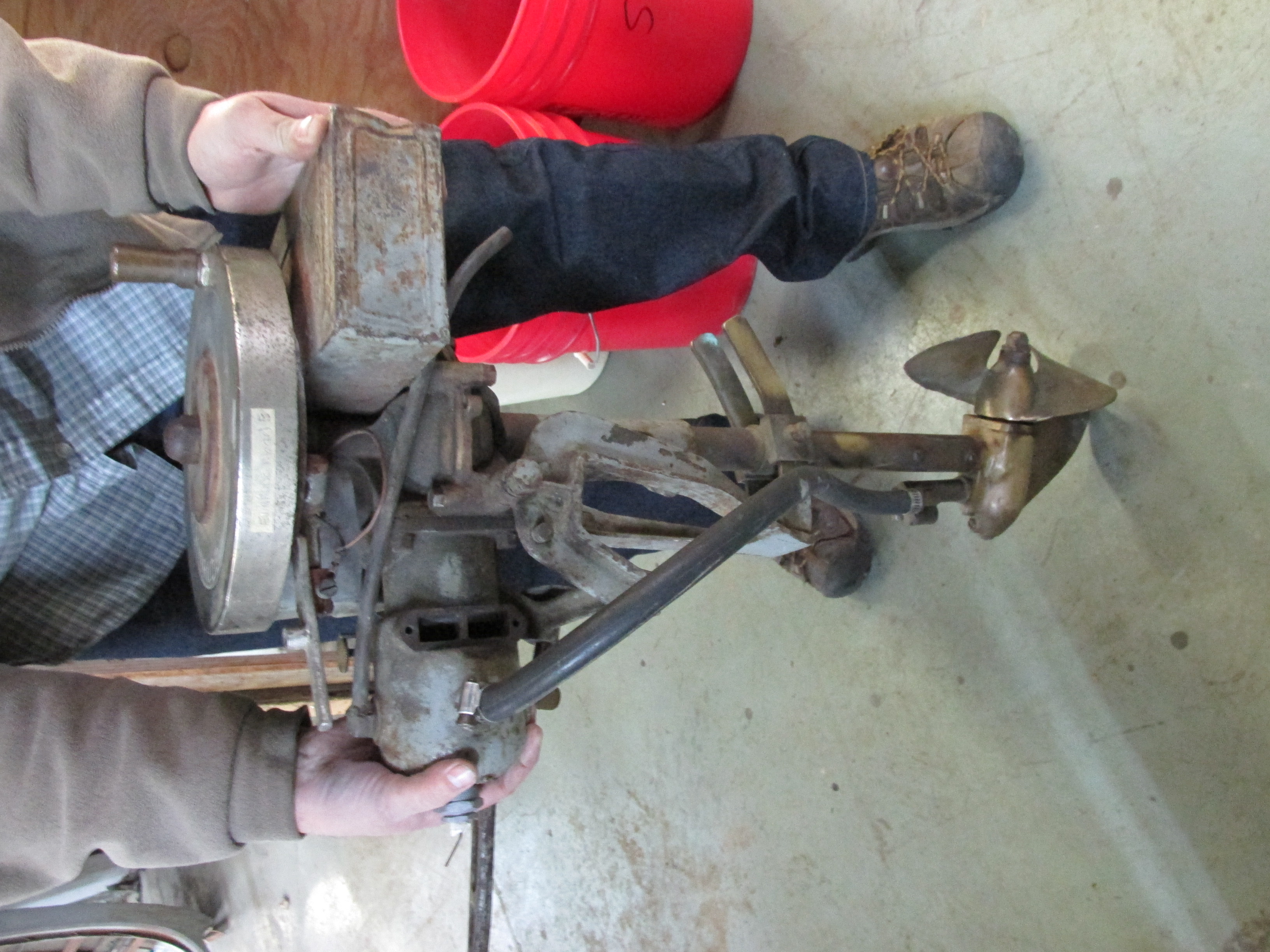
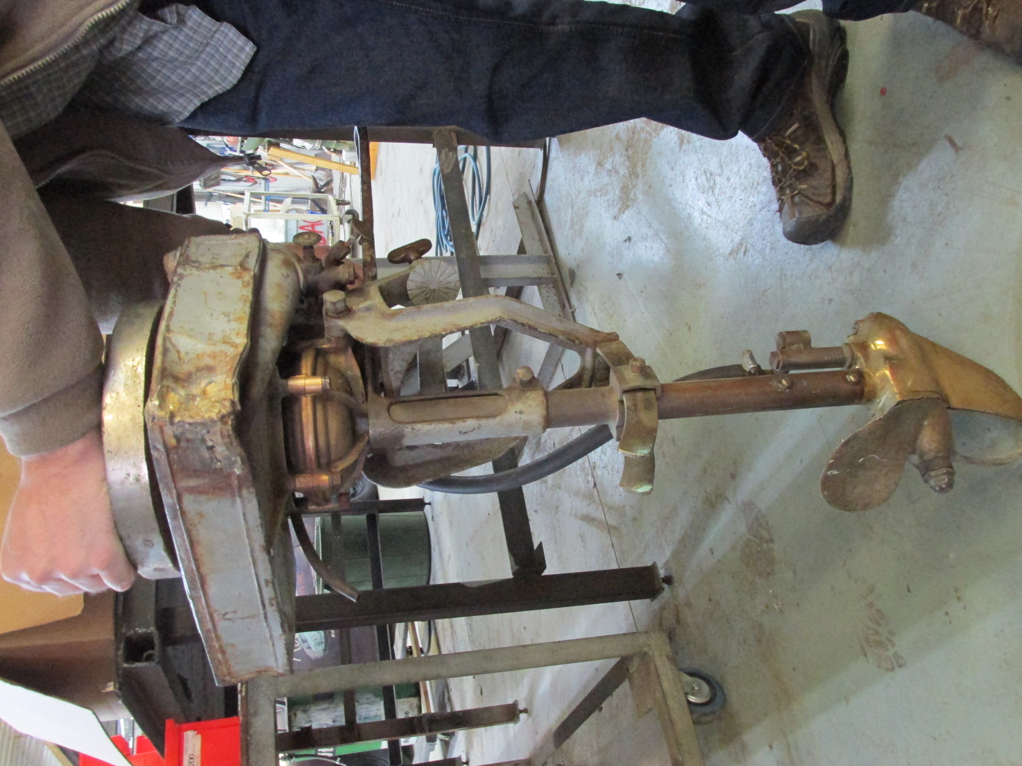
Brought home this 1914 Evinrude the other day. It’s hurtin’ fer certain, but not beyond hope. Gas tank looks like its bounced around some, the entire exhaust is missing, and it lacks one transom screw & pad, but the rest is mostly there. it spins nice and free, compression is really good, and the lower unit might be useable as-is.
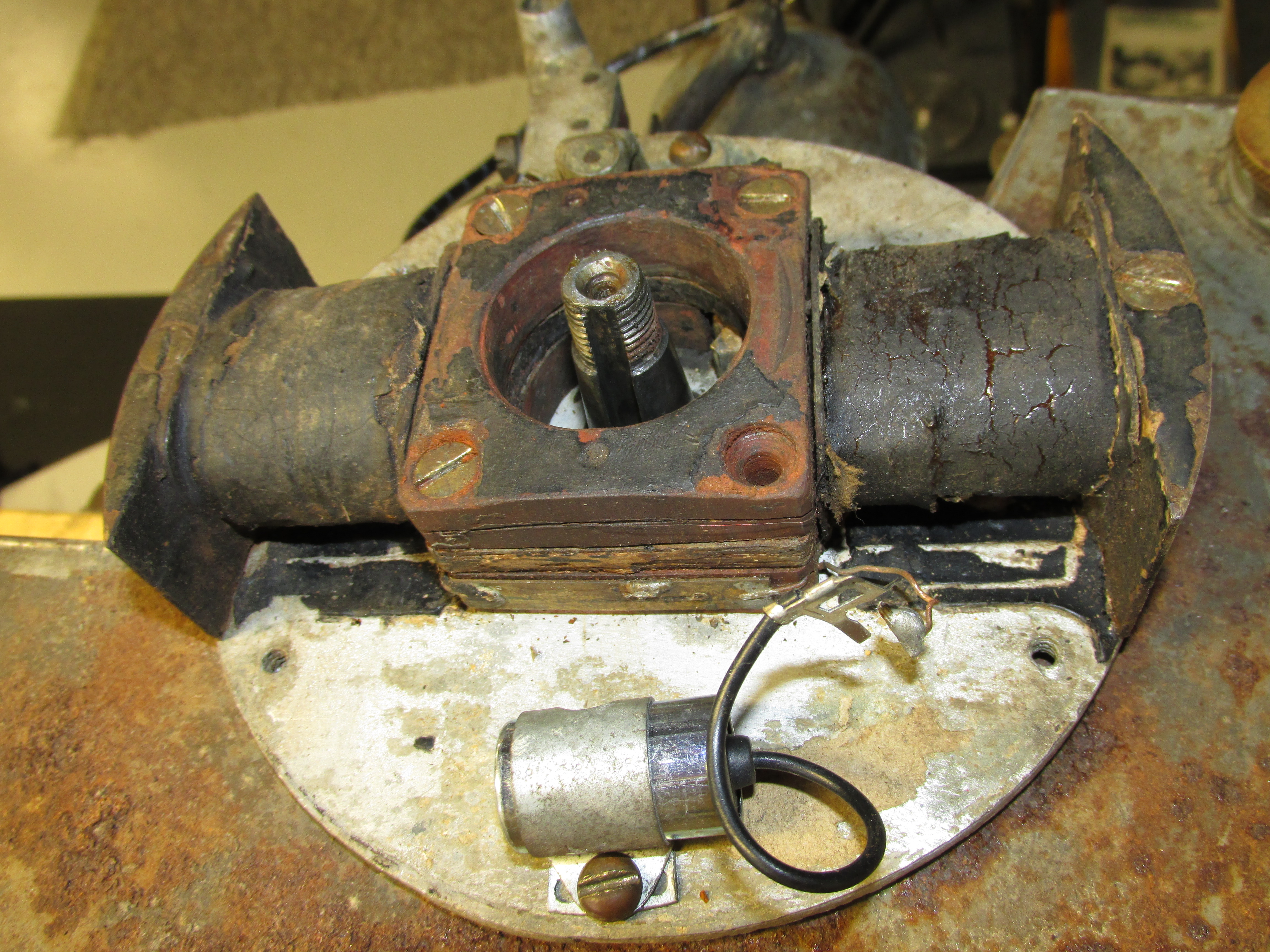
Worked on it some today, and have failed to get it to generate any type of spark, even though it’s got the original cracked coil in it (that apparently is ultra desirable, heehee). Anyway, I’ve never worked on one of these, so this is the first time for me to see a 1914 Evinrude coil in person. Odd sort of set-up, but typical of flywheel magneto motors of that era. So far, rudimentary testing shows that there is continuity between the small bare wires that are routed about the stack of laminations in the centre. I’ve not detected continuity when testing the high tension lead, but I’m not exactly sure how to go about it either.
Hoping that somebody can make a suggestion on the proper way to test this coil. I was not comfortable with trying a coil power test with the Merc-O-tronic until I know for sure how to hook it up. The Model 98 manual seems to lack a diagram for this magneto… must be some mistake…
Best,
PM T2He's livin' in his own private Idaho..... I hope to go out quietly in my sleep, like my grand-dad did..... and not screaming, like the passengers in his car...
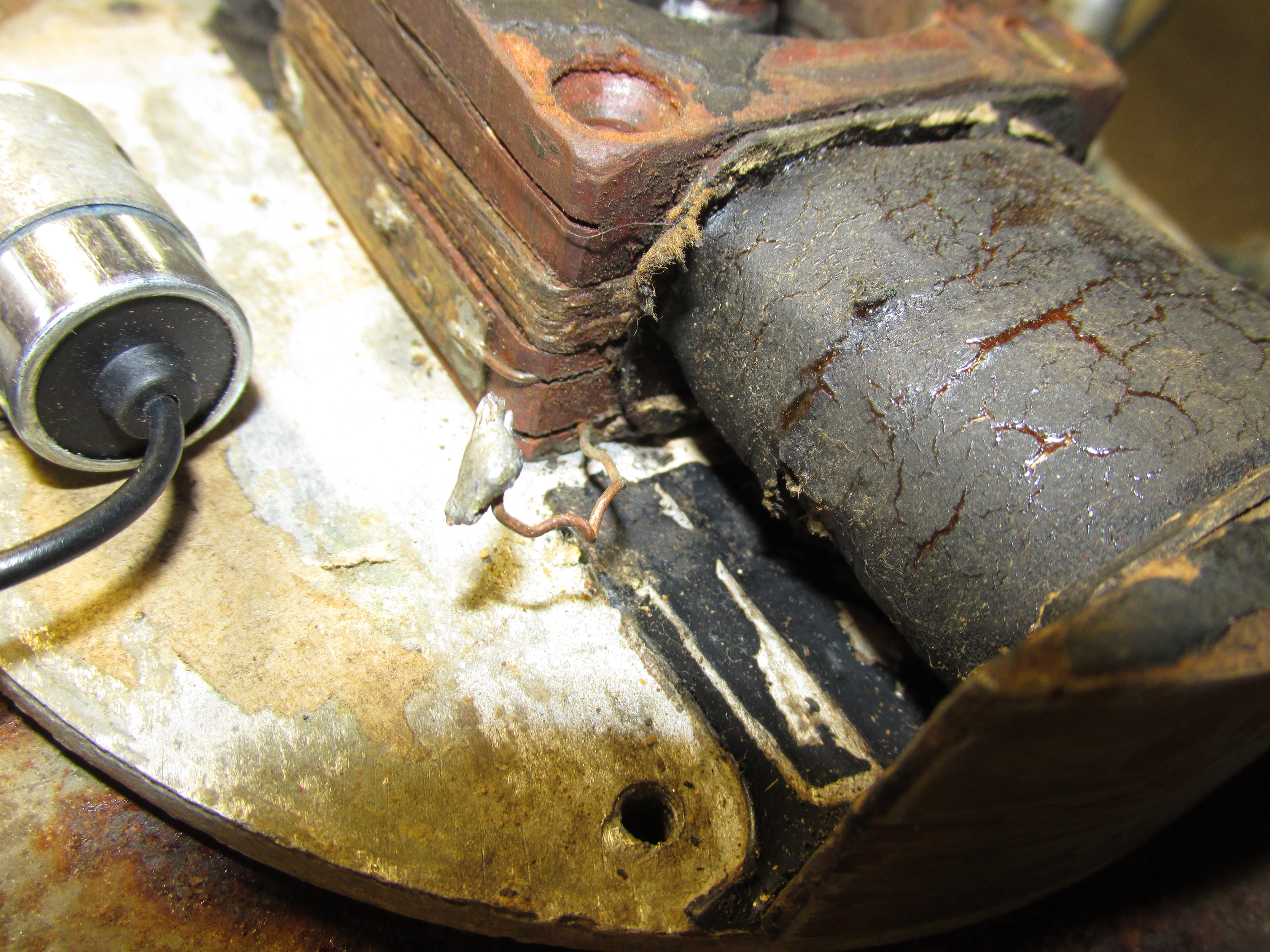
January 23, 2017 at 3:56 am #51537That is interesting. I don’t know what’s happening here. I assume the bare wire with the glob of solder is the primary. Are the points in the center with the crank or on the other side of the coil. Its pretty cool.
Wayne
Upper Canada Chapteruccaomci.com
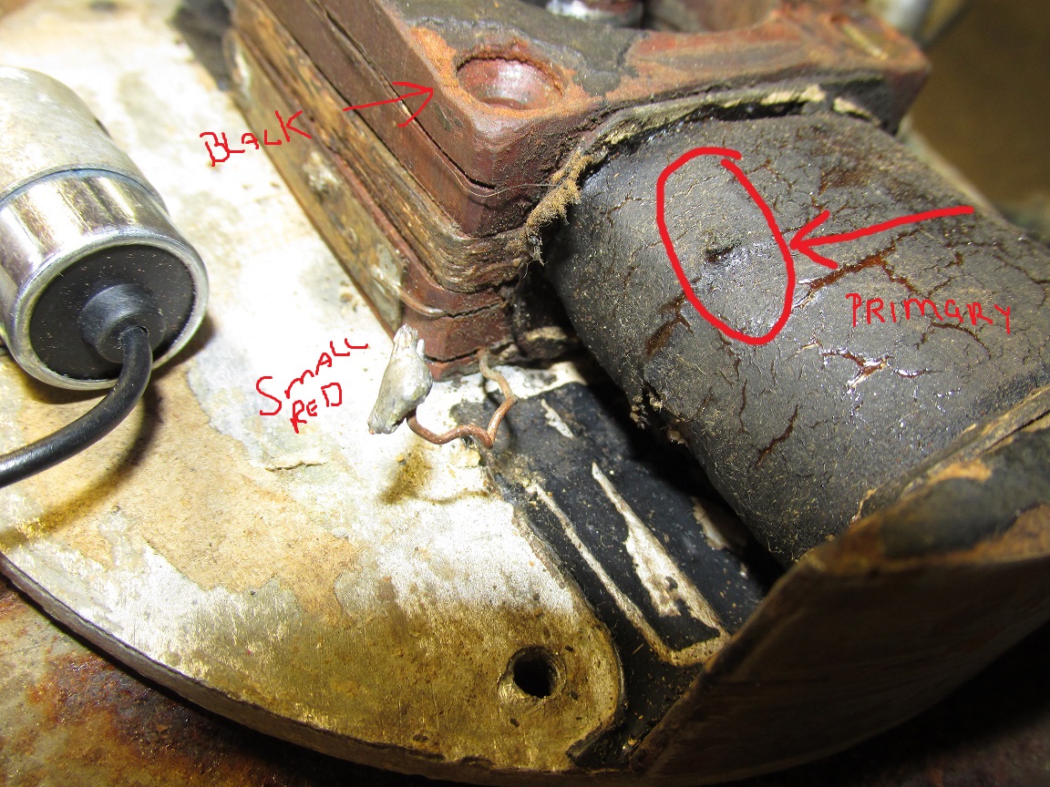
January 23, 2017 at 11:38 am #51550Try what I have cobbled together here in this photo:
3 wires to check from the MercOtronic.
small red
small black
large red(primary)
Try connecting them as I have marked on this photo.The glob of solder is, or if memory serves, from the old condenser??? Mine was rectangular and had same globs on it, connect the small red lead from the tester to that one.
small black to location noted on picture.
And large red from tester to spot marked as such.The spot is right where I got spark on my 1914 coil, I surmise it was to have had a tab to attach the plug lead going down to the plug. Mine was missing but that is where I got spark.
http://www.richardsoutboardtools.com
classicomctools@gmail.comJanuary 23, 2017 at 11:41 am #51551If I had my old coil in front of me I could confirm this, but Todd Mizen owns it now…
http://www.richardsoutboardtools.com
classicomctools@gmail.com -
AuthorPosts
- You must be logged in to reply to this topic.