Home › Forum › Ask A Member › 1936 Evinrude Sportfour Imperial, testing the solid state cutout relay
- This topic has 6 replies, 5 voices, and was last updated 5 months, 1 week ago by
 Buccaneer.
-
AuthorPosts
-
October 27, 2025 at 5:32 pm #300988
I had my old points type cutout relay changed to solid state.
The old case was gutted and a diode installed.
The same person previously set me up with a solid state voltage regulator.
It seems to charge okay, and now I don’t have to worry about the
cutout relay’s points sticking and melting down the motor / generator.I still have to figure out the voltage going to the ignition coil.
Voltage going into the coil (after the 3 ohm resistor) is around 11 volts.
Maybe I need to measure it on the outlet side of the coil, going to the points?
Mr. Ohm’s Law and I don’t get along!VIDEO…..
https://youtu.be/tAX9YWPth3MI got the decal installed on the tank today. I opted “not” to install the
smaller one atop of the gas tank (operating instructions, etc.) as it
doesn’t really jive 100% for an Owen Dyneto equipped motor, and
not sure I like the silver decal on a silver tank.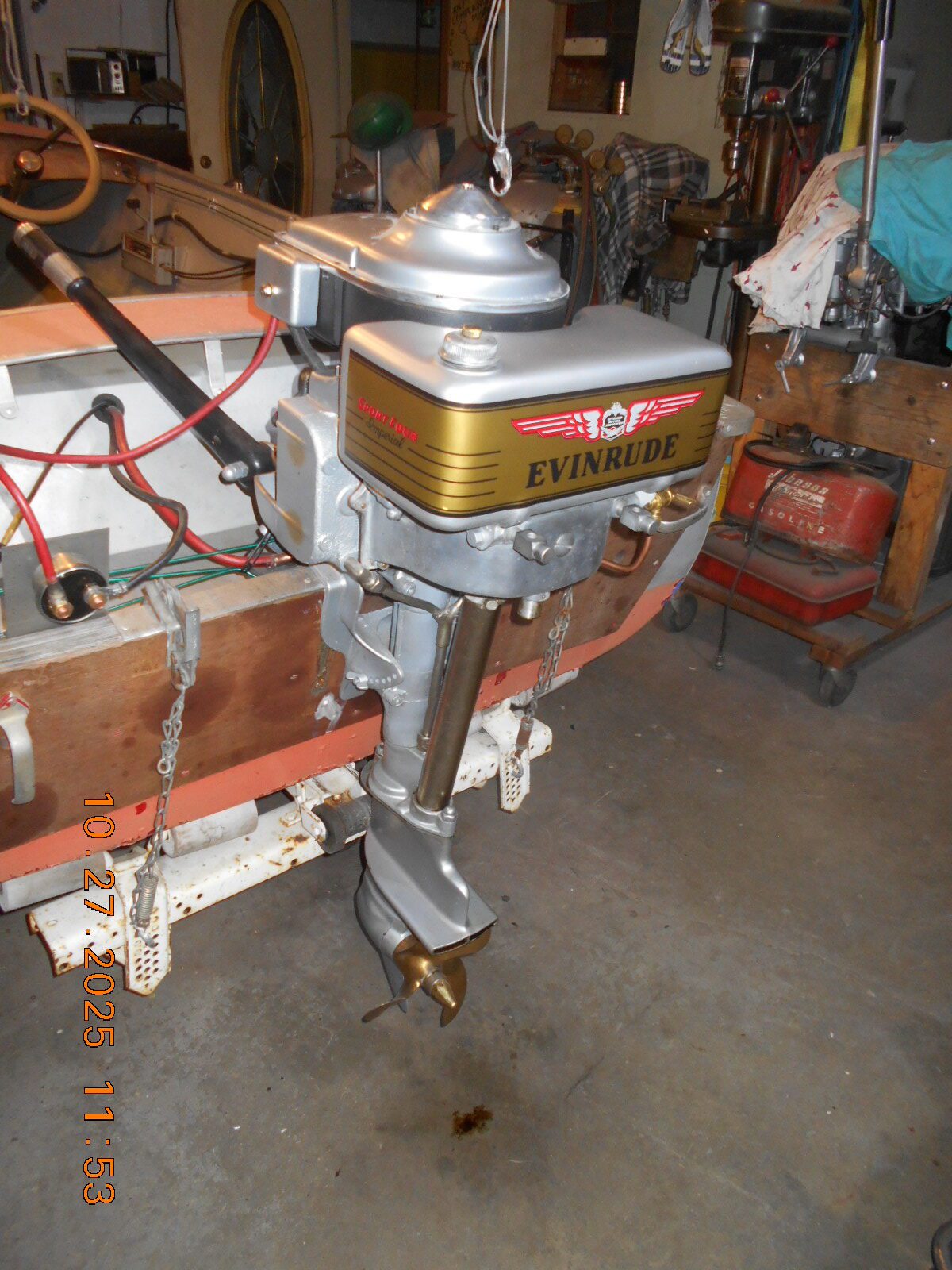
Prepare to be boarded!
October 27, 2025 at 9:10 pm #301000You do fine work!
Well I am only going by what I remember working on the old Chryslers with the ballast resistors. If I remember correctly, I believe the resistor cut the voltage down to about 9 volts. I may be wrong but that is what I remember. What if you took the original resistor that was in the motor and hook it up to a battery positive terminal and the other side through a volt meter back to the battery negative terminal. Read the voltage and see what it drops to. If it is close to 11 volts, you may be good. If it drops it lower to 6-9 volts, get a different ohm ballast resistor and retest.
October 27, 2025 at 10:28 pm #301002From what I read, the resistor in an ignition system is sized taking
in consideration the total resistance of the coil and the resistor.
The original resistor, as strange “stacked” affair that went through
the bottom of the electrical gear pan, via insulators, was in sad
shape, but it tested at around 2 ohms resistance.I first tried a 1.7 ohm automotive resistor, and the running volts at
the coil “Bat” connection was 10.37 volts, using a digital meter.On this last test, I used a 3 ohm resistor and an old analog volt meter,
and it read about 11 volts.
I think I should test the voltage on the outlet of the coil’s primary
and see what’s actually going to the points.Prepare to be boarded!
October 27, 2025 at 10:47 pm #301004
This motor sure ended up in the right place.

A "Boathouse Repair" is one thats done without having tools or the skills to do it properly.
October 28, 2025 at 8:48 am #301009This motor sure ended up in the right place.
I’ll second that! WOW! that baby is perrrty!
dale
October 28, 2025 at 12:41 pm #301010Outstanding restoration!
Bob
1937 Champion D2C Deluxe Lite Twin
1954 Johnson CD-11
1955 Johnson QD-16
1957 Evinrude Fastwin 18
1957 Evinrude 3022
1958 Johnson QD-19
1958 Johnson FD-12
1959 Johnson QD-20
1982 Evinrude 25hp“Every 20 minute job is only a broken bolt away from a 3-day project.”
"Every time you remove a broken or seized bolt an angel gets his wings."October 28, 2025 at 1:49 pm #301015The decal looks great from six feet away. From two feet you can
observe my struggles!
I did use a wetting solution. On the first half of the decal, I
felt that I wetted it too much, and I was having mucho trouble
getting the bubbles out with my scrapper.
On the second half of the decal, I used less wetting solution,
and struggled with positioning near the corner, and ended up
with a small crease.
A couple of bubbles I gave up on and used a needle to drain them.
All in all, the typical troubles and results for me, but also,
“good enough for me”.Prepare to be boarded!
-
AuthorPosts
- You must be logged in to reply to this topic.