Home › Forum › Ask A Member › 1936 Sportfour Imperial coil and condensers
- This topic has 3 replies, 3 voices, and was last updated 7 months, 3 weeks ago by
 Buccaneer.
-
AuthorPosts
-
August 13, 2025 at 5:23 pm #298943
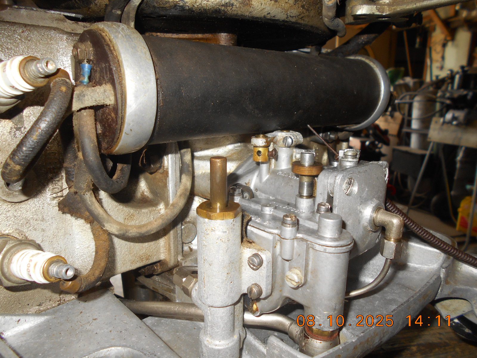
The coil on this one seems to test okay on the ohm meter, but the plug
wires sticking out of it aren’t the best of shape.Any one have a wiring diagram on how the four cylinder coils are
wired up, and what’s actually inside the tube? I.E., one coil, two coils, etc?
The old condensers are external, and test out at .92 and 1.4 mfds……
way out of whack I presume????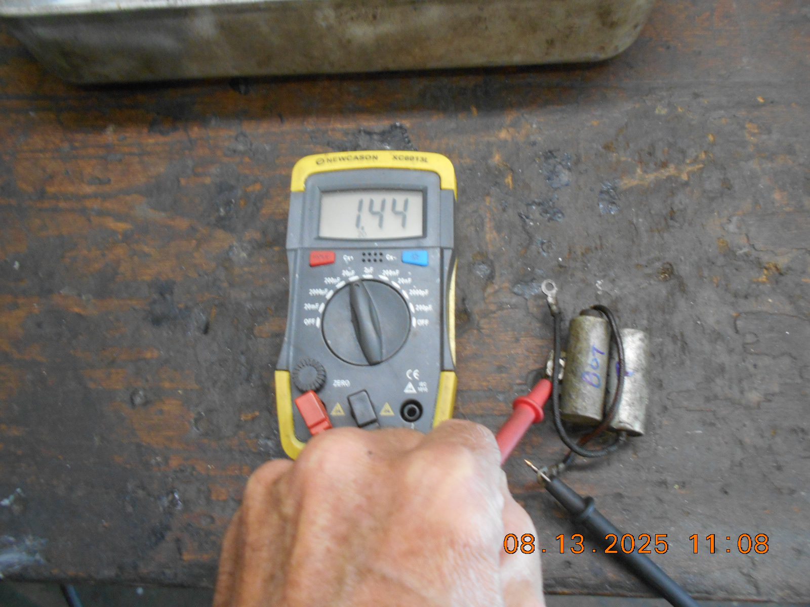
Prepare to be boarded!
August 13, 2025 at 8:04 pm #298951chat gpt stuff ……….try it to get a better display of this info
<article class=”text-token-text-primary w-full focus:outline-none scroll-mt-(–header-height)” dir=”auto” tabindex=”-1″ data-turn-id=”7434eb4d-d3be-47d0-abc7-735ace4e2944″ data-testid=”conversation-turn-1″ data-scroll-anchor=”false” data-turn=”user”>
do you have a wiring diagram for 1936 Sportfour outboard</article><article class=”text-token-text-primary w-full focus:outline-none scroll-mt-[calc(var(–header-height)+min(200px,max(70px,20svh)))]” dir=”auto” tabindex=”-1″ data-turn-id=”895eb734-9842-4b06-ade8-9bf57ca62523″ data-testid=”conversation-turn-2″ data-scroll-anchor=”true” data-turn=”assistant”>
ChatGPT a dit :
<button class=”flex w-full items-center gap-0.5″>Réflexion durant 25s</button>Short answer: I don’t have a factory scan I can show here, but I can give you a correct, working schematic for the 1936 Evinrude Sportfour. There were two common wiring setups that year:
-
the plain magneto-ignition (no electric start), and
-
the Imperial Electric version (Model 9017) that used a starter-generator and a regulator (often wired 12-volt, frequently with positive ground on surviving examples).
Below are clean, readable schematics for both.
<hr data-start=”476″ data-end=”479″ />
A) 1936 Sportfour — magneto ignition (no electric start)
Uses a flywheel magneto with two sets of breaker points/coils, and a simple “magneto-kill” switch that grounds the primary to stop the engine.
[Magneto Stator]
|---- Primary coil A ----> to breaker A -> to condenser A -> to magneto ground
|---- Primary coil B ----> to breaker B -> to condenser B -> to magneto ground
|
+---- "KILL" lead (usually cloth-insulated single wire)
|
+----[Momentary or toggle STOP switch]-----> Engine block (ground)Spark plug leads from secondary coils go directly to the four plugs.
No battery. No charging. One wire from magneto to a normally-open stop switch that grounds to kill.
How to wire it:
-
Run a single insulated wire from the magneto’s “kill” terminal to a normally-open stop switch at the tiller/plate.
-
Other switch terminal to clean engine ground.
-
That’s it electrically; everything else is inside the magneto.
<hr data-start=”1454″ data-end=”1457″ />
B) 1936 Sportfour Imperial Electric (Model 9017) — starter-generator + charge control
Period hardware typically used an Owen/Dyneto-style starter-generator, a cut-out/regulator, an ammeter, and a battery. Many were 12 V and often positive-ground (confirm on your tag/regulator before wiring).
(Often POSITIVE GROUND system)
________
Engine Block ----| + |---- Battery (+) <-- often tied to block/frame
| Batt |
|______|
|
| Battery (–) cable to:
v
[Ammeter] (optional but period-correct)
|
[Starter Switch / Foot or Toggle]
|
[Starter Relay/Solenoid]* (some used a heavy manual contact instead)
|
+-----+---------------------------+
| |
[Starter/Generator] [Regulator/Cut-out]
| D (armature output) | GEN/ARM
| F (field) -------------------+-- F
| | BAT -> to ammeter/battery (– post)
| | (sometimes an "L" or "SW" lead to lights)
+---------------------------------+Kill/ignition: same as non-electric—magneto “KILL” lead to a switch that grounds to stop.
*If no solenoid, the start switch directly closes the heavy starter contactor supplied on some units.
Notes that matter on the Imperial Electric:
-
Surviving motors often show a 12 V plate and have been found wired positive ground (block to +). Verify yours—don’t assume. Look for the Owen/Dyneto (or similar) tag and markings before you hook up a battery. aomci.org
-
Owners discussing the 1936 Sportfour Imperial Electric (9017) confirm the configuration and period charge control; there’s also chatter about the toggle controlling charge rate vs. on/off. aomci.org+1
-
The all-models 1911–1942 Evinrude/Elto service literature lists Sportfour and the electric-start variant, helpful for specs and generic wiring practice (magneto kill, cut-out/regulator placement), even when a model-specific page isn’t shown. marinemanuals.com
<hr data-start=”3888″ data-end=”3891″ />
Practical tips before you wire
-
Confirm polarity and voltage on your generator/regulator tags before connecting a battery. Wrong polarity can toast the regulator in seconds. aomci.org
-
If your regulator has terminals marked BAT / GEN (or ARM) / FLD / (L or SW), wire as in diagram B: BAT back to ammeter/battery, GEN/ARM to generator armature post (D), FLD to generator field (F).
-
The stop switch always just grounds the magneto’s primary—no battery on that circuit.
-
Cloth insulation from the 1930s is fragile. Replace with modern tinned-marine wire but keep the runs and hardware locations true to original.
</article>
Joining AOMCI has priviledges 🙂
August 13, 2025 at 10:09 pm #298952I have coils that Jim Ross gave to me that he removed from a Quad coil casing, I’ll dig them out in the morning, but as I recall its two coils inside one casing, and I bet the coils still smell like gasoline because that’s what he used to dissolve the pitch that they packed the coil casing with.
PM T2
He's livin' in his own private Idaho..... I hope to go out quietly in my sleep, like my grand-dad did..... and not screaming, like the passengers in his car...
August 13, 2025 at 10:56 pm #298953Thanks for all the information. Will try to decipher in the morning when
I’m more awake!Prepare to be boarded!
-
-
AuthorPosts
- You must be logged in to reply to this topic.