Home › Forum › Ask A Member › 1936 Sportfour Imperial Electric, Model 9017
- This topic has 16 replies, 3 voices, and was last updated 7 months, 3 weeks ago by
 Buccaneer.
-
AuthorPosts
-
August 10, 2025 at 6:19 pm #298846
Thanks Tubs and Chris.
I pulled the top covers to take a peek today.
Interesting for sure. I’ll be tracing wires and making my own
crude diagram before I take anything apart.The Owen data tag on mine is marked “12 Volt”, and someone
had marked the ground terminal as “Positive”. That might
be fun finding a new voltage regulator if needed?I wonder how the starting motor’s armature / rotor is coupled
to the crankshaft?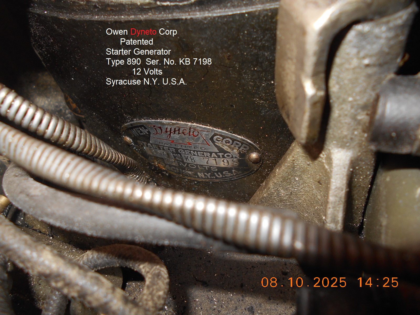
Prepare to be boarded!
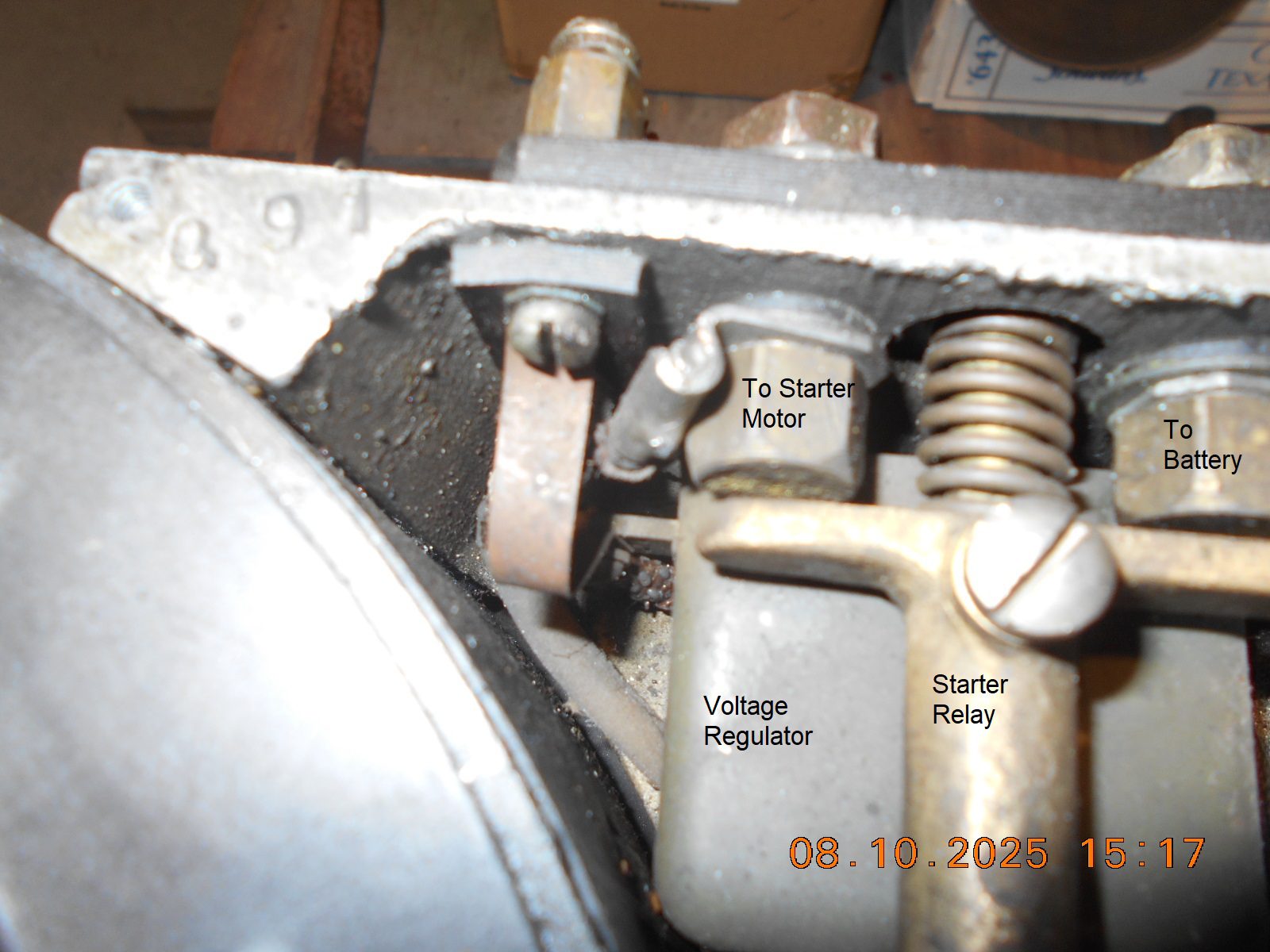
August 10, 2025 at 9:21 pm #298853In looking at my photos again, and from what I observed in the garage,
the starter relay must be activated manually by the magneto advance lever,
as there’s no electric coil to plunge the relay “closed in”…… just a coil
spring to return the contactor “open”.
There seems to be no tension on the mag lever to hold the advance lever
in a particular spot, but maybe there’s some device on the mag plate
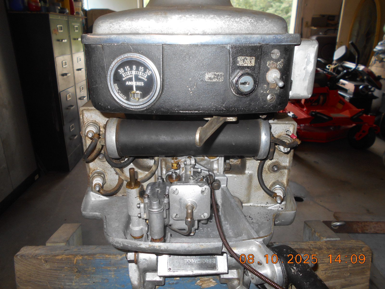
that needs attention.I thought perhaps the operation decal atop the gas tank would give some
clues, but alas, it’s not the correct decal, as it mentions winding the
rope around the starter plate. 🙁Anyone know whose Speedifour this is? I guess it was at Tomahawk a few
years ago.
Lots to learn.
Prepare to be boarded!
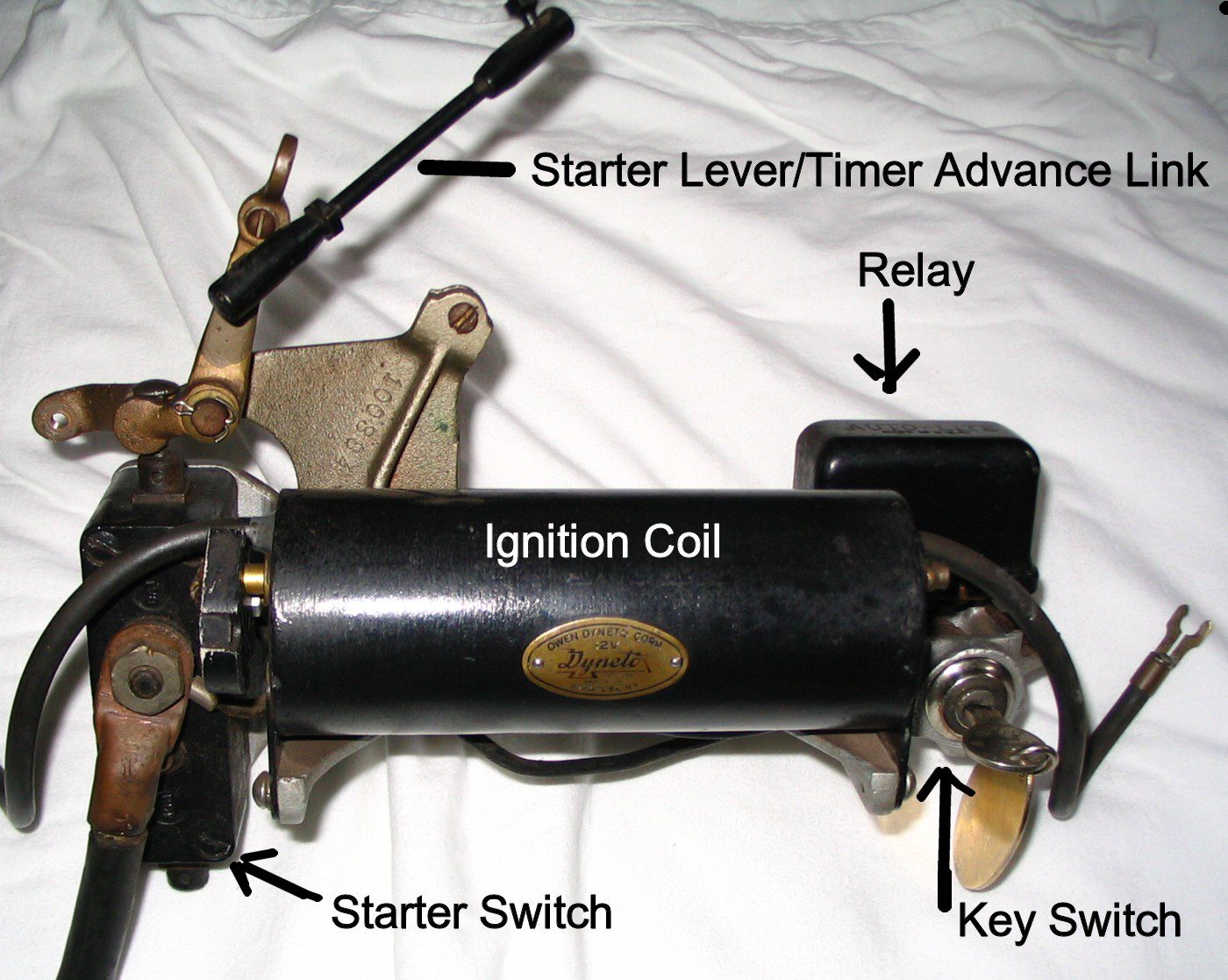
August 12, 2025 at 4:34 pm #298886The lever sticking out is not a magneto or timer advance, its just a starter lever, that’s all it does.
Its correct that these motors were positive ground 12 volt, except the Johnson SE and VE, which were six volt units. Don’t ask me why because I can’t tell you.
The rotor of the starter-generator is seated on the crankshaft the same was a flywheel is mounted. The rotor is the flywheel on these motors, thus is tightened in place by the usual flywheel nut. Its buried within the rotor beneath the timer plate.
FWIW, Sam Vance and I had a long discussion about the voltage regulators on these motors, and we were both of the opinion that the longevity of the unit is better served with the voltage regulator taken out of the circuit and the charging circuit disabled. If the points on the regulator stick together, and you happen to be running at high speeds on a hot day, it can cause an overcharge/overheat condition with the distinct possibility of the rotor windings becoming hot enough to soften and throw the solder that keeps things together. If that happens, your engine stops instantly and you have a rats nest of copper winding to sort out and remove. Needless to say, your Owen-Dyneto unit is scrap metal at that point. It’s the leading cause of these units having been removed and replaced with flywheel magnetos. There are many examples of Evinrude, Elto, and Johnson motors out there that have model numbers that show it to be an electric start but the motor is fitted with conventional flywheel or battery ignitions.
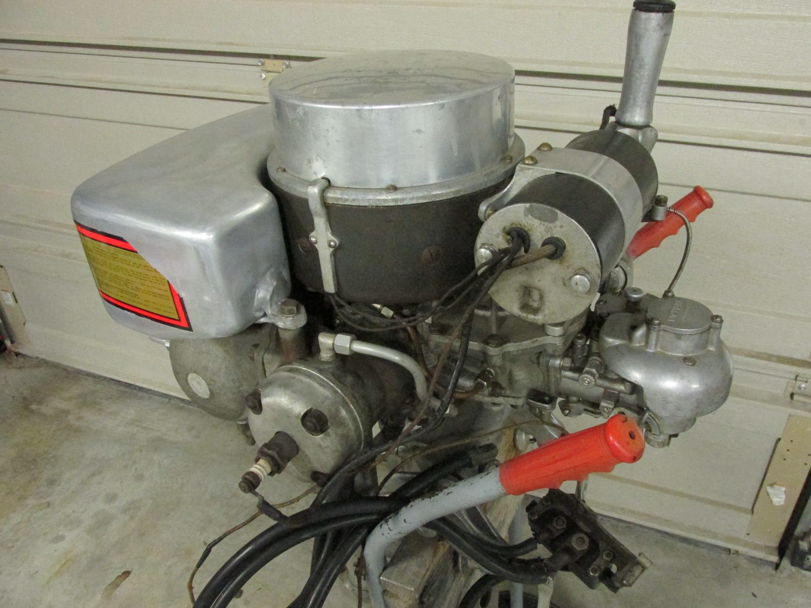
Attaching pix of a Johnson SE-50 just for shits and giggles.
Hope this helps.
Best,
PM T2He's livin' in his own private Idaho..... I hope to go out quietly in my sleep, like my grand-dad did..... and not screaming, like the passengers in his car...
August 12, 2025 at 6:26 pm #298894Thanks for the reply.
Regarding the start lever: My lever does engage the motor contacts,
but rotates the magneto changing the timing. The lever flops about
rather easily, and hence the magneto rotates, changing the timing.
I’d have to study if further, but perhaps the lever is retarding the timing
while starting, and once released, advances it.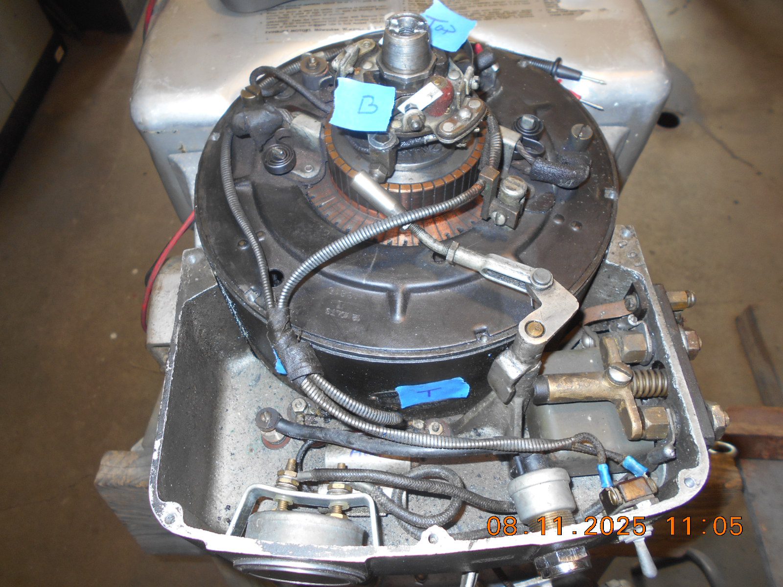
I understand what you’re saying about the regulator.
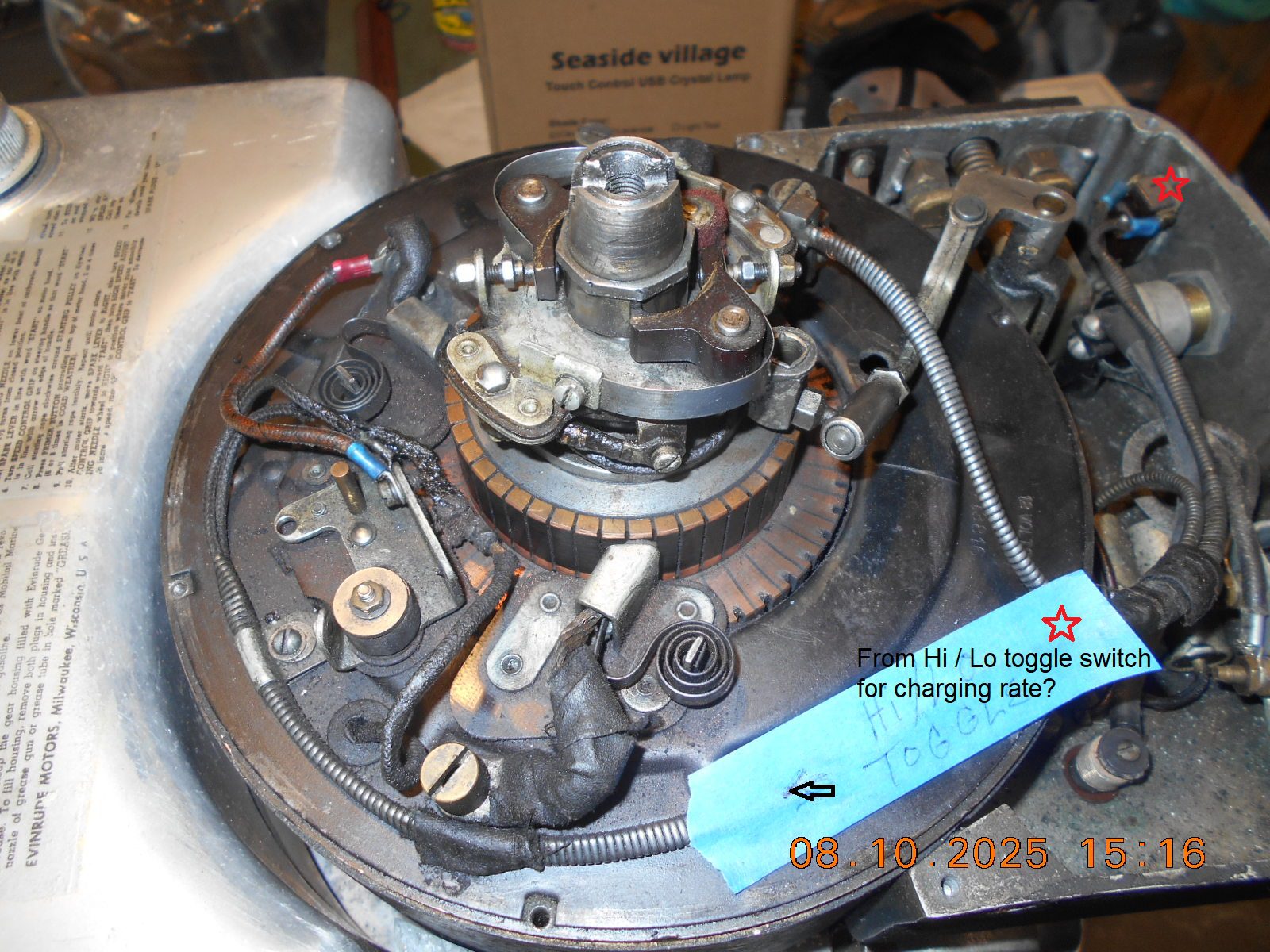
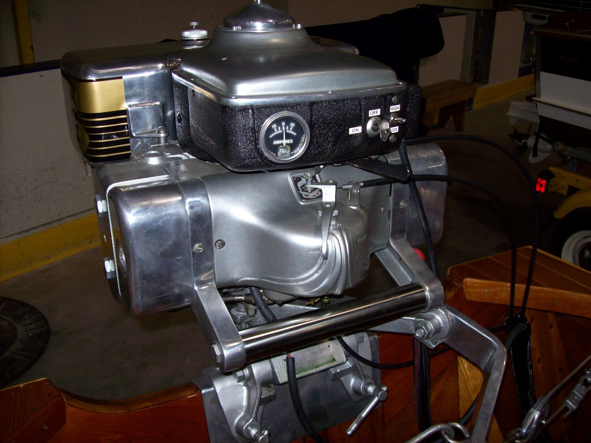
Any idea what exactly the toggle switch does?
Mine is a simple two pole switch, either on or off.
I’m not sure if it’s HI and LO charging rate, or just
shuts charging on and off.Thanks.
Prepare to be boarded!
August 12, 2025 at 10:02 pm #298897I think you will find the toggle switch controls the power to the ignition system. Thats how it should be at any rate.
You’re correct about the timing tho, the starting mechanism does retard it to start then allows it to advance once the starter lever is released. I haven’t worked on my electric Jr Quad very much so I got discombooberated there a bit, my bad. But what I was driving at previously is that once the motor is running, its not a lever to control the speed, thats what I was trying to get across.
At least with the top covers and shrouds removed, you can see the original round armature housing which is what you see on the outboards before Evinrude-Elto went to the “verandah” style starter housing, as Sam Vance referred to it. I’ve never had an Owen-Dyneto equipped motor that had a switch that set a “high” or “low” rate of charging. Charging was either on or it wasn’t, as it was always understood that it was an automatic cutout point that the electrical system controlled relative to engine RPM. At speeds above (approximately) 1000-1200 RPM, the charging system kicked in and was governed thereafter by the regulator circuit. My Super C electrics have a three position switch; One is RUN, the middle one is “CHARGE” and the third is “START”. They were also equipped with a key switch for turning the battery juice on and off. The switch on the later model electrics was a lil different, as you’ve found out.
Hope this helps.
Best,
PM T2He's livin' in his own private Idaho..... I hope to go out quietly in my sleep, like my grand-dad did..... and not screaming, like the passengers in his car...
August 12, 2025 at 10:45 pm #298900I replied but it “crashed”. Will try again tomorrow.
Prepare to be boarded!
August 13, 2025 at 8:10 am #298904PM T2, regarding……
I think you will find the toggle switch controls the power to the ignition system. Thats how it should be at any rate.
My toggle switch, a simple two pole, “ON / OFF” switch, does not tie into the ignition system.
Both leads from the switch go directly atop of the Owen motor / generator terminals, and
one wire then goes thru the endcap of the unit.
I got the idea of a “HI / LO” charging switch, from the photo posted above of the Speedifour.Charging was either on or it wasn’t, as it was always understood that it was an automatic cutout point that the electrical system controlled relative to engine RPM. At speeds above (approximately) 1000-1200 RPM, the charging system kicked in and was governed thereafter by the regulator circuit.
Not sure what magic causes one of those units to start charging around 1000 ish rpm’s, but perhaps
that’s when the residual magnetism builds up enough to excite it into charging?My Super C electrics have a three position switch; One is RUN, the middle one is “CHARGE” and the third is “START”. They were also equipped with a key switch for turning the battery juice on and off. The switch on the later model electrics was a lil different, as you’ve found out.
My key switch’s (key missing) sole purpose appears to be to power the coil, via a 100 ohm resistor,
which I presume is to cut the voltage down at the point sets. Will have to study the ohms
law to see if 100 ohms makes any sense.Thanks!
Prepare to be boarded!
-
AuthorPosts
- You must be logged in to reply to this topic.