Home › Forum › Ask A Member › 54Evinrude Big Twin crankcase
- This topic has 38 replies, 13 voices, and was last updated 10 years ago by
ADAM GIBB.
-
AuthorPosts
-
February 8, 2016 at 11:12 pm #31654
Fleetwin, If there was positive pressure in front of the reed plate, seems like it would cause bubbling at the bearing o-ring groove. Last fall I turned my Johnson motor over with a wrench with WD40 covering the top of the seal. Bubbles came up through the vertical slot. I will change the pressure valve for the tank.
February 9, 2016 at 12:40 am #31661That’s nice and clean inside!
 [/URL]
 February 9, 2016 at 2:41 pm #31689
here are some more pictures I uploaded for Charlie:

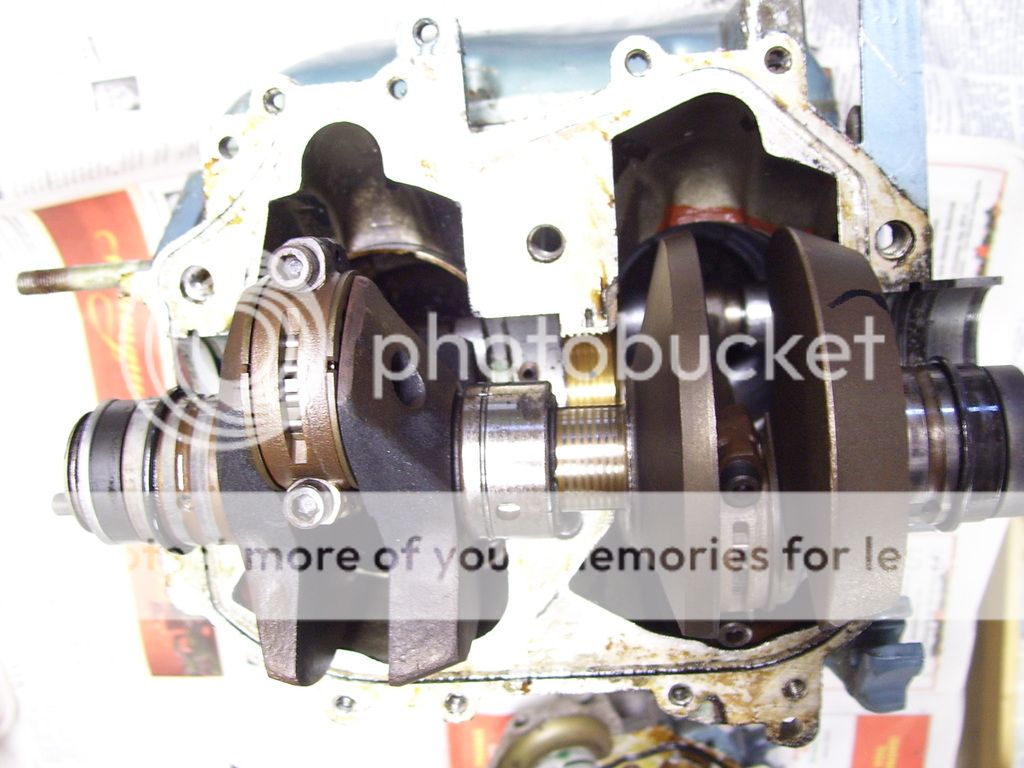


Well, I am confused, as usual…This engine seems to use a combination of the oring around the upper bearing and the vacuum drain systems…
My question is: does that vacuum groove in the crankcase go into the oring groove? Kinda hard to tell by the pictures. If so, this seems like an engineering "mistake". The dark wet surface on the crankcase shows pretty clearly where the leak is, sure does not appear to be a crankcase sealing problem. I will have to look closer at the pictures…February 9, 2016 at 7:14 pm #31696OK, here are some more pictures of the crankcase drain passages on Charlie’s engine:


OK, it is hard to see, but the groove in the crankcase does extend into the groove where the oring was…Hard to see, but the little vacuum port is in that groove where the oring was…In my feeble mind, I’m thinking that oring does not belong there. Having the oring in the groove kinda plugs up the vacuum port and system efficiency. So, to me, having the oring in place was either a manufacturing or engineering oversight, I don’t think this powerhead has ever been apart before. I’m guessing this engine is in such nice shape cuz it was rarely used due to the constant oil fouling of the mag plate…
What do you guys think? I wish that this crazy system was used in conjunction with the conventional oring sealing. In other words leave the crankcase groove above the conventional oring groove, along with the vacuum port. They could have even added another circular groove around the upper bearing as well…February 13, 2016 at 2:21 am #31862Well, the plan is to put the motor together without an o-ring on the top bearing as that is apparently the latest configuration. Many thanks to all for the advice and especially to fleetwin and F. Robb.
VR
CharlieFebruary 23, 2016 at 7:00 pm #32400Bolted the crankcase together this morning then removed the head as one spark plug thread is stripped. The port side of each bore is shiny smooth. The starboard side of each bore has lots of shallow scratches. I really do not want to open the crankcase again but is condition of these bores common?
Thank you.
http://i77.photobucket.com/albums/j66/c … 1456167090
http://i77.photobucket.com/albums/j66/c … 1456167094
http://i77.photobucket.com/albums/j66/c … 1456167094
http://i77.photobucket.com/albums/j66/c … 1456167094February 23, 2016 at 9:10 pm #32404There should not be an o ring on the top bearing for that model. Many times, one gets installed when they are opened up.
February 23, 2016 at 9:28 pm #32406quote OLCAH:Bolted the crankcase together this morning then removed the head as one spark plug thread is stripped. The port side of each bore is shiny smooth. The starboard side of each bore has lots of shallow scratches. I really do not want to open the crankcase again but is condition of these bores common?
Thank you.
http://i77.photobucket.com/albums/j66/c … 1456167090
http://i77.photobucket.com/albums/j66/c … 1456167094
http://i77.photobucket.com/albums/j66/c … 1456167094
http://i77.photobucket.com/albums/j66/c … 1456167094Well, can’t really see much in your pictures. Minor "scratches" are usually not a cause for concern, is there any evidence of aluminum scuffing on the cylinder walls? The intake bypass covers can easily be removed on the port side to get a closer look at the rings/piston skirts. Removing the exhaust cover shouldn’t be too tough on a fresh water motor, but cleaning up the gasket surfaces/carbon is time consuming, but removing the cover will give you a better look at the exhaust side of the pistons/rings.
I usually use some fine emery to clean up and remove the glaze from the cylinder walls. A little unethical, but works just fine.
Again, I can’t make any judgements based on your pictures because the cylinder walls don’t show up well. Take some more pictures if you can…D
PS, you can see the lower exhaust side of one piston just by flipping the powerhead on its side and looking up into the exhaust chamber if the powerhead is still off the exhaust housing….February 24, 2016 at 1:54 am #32424Here are more photos.
http://i77.photobucket.com/albums/j66/c … 1456191343
http://i77.photobucket.com/albums/j66/c … 1456191339
http://i77.photobucket.com/albums/j66/c … 1456191343
http://i77.photobucket.com/albums/j66/c … 1456191343
http://i77.photobucket.com/albums/j66/c … 1456191343
http://i77.photobucket.com/albums/j66/c … 1456191343
The scratches catch a fingernail drawn across. I estimate they are 0.005 deep. Does this seem ok?February 24, 2016 at 2:01 am #32425Charlie,
I am thinking(hoping) that the pictures make it look worse than it is. Any idea of compression numbers yet? I think that will tell you what you need to know.
-
AuthorPosts


- You must be logged in to reply to this topic.