Home › Forum › Ask A Member › Coil conversion
- This topic has 22 replies, 7 voices, and was last updated 4 years, 10 months ago by
JACQUES.
-
AuthorPosts
-
May 19, 2021 at 4:40 pm #238611
That’s correct Steve. It is a connector which combines the primary lead and the cut out lead and connects them to the points. It’s an odd set up due to wire length and position of the mount on the points. The wires were (and now are again) crimped bacwards in the connector.
As Tom says, if that connector, however, IS touching the inside of the flywheel as it spins around, then it would be a short, right? But if that were the case, I would have no spark, correct?
Scott
-
This reply was modified 4 years, 10 months ago by
opposedtwin.
-
This reply was modified 4 years, 10 months ago by
May 19, 2021 at 8:53 pm #238625Why not just move it and eliminate the possibility?
T
May 20, 2021 at 5:58 am #238639May I also suggest humbly, reattempting that solder job.
With no disrespect, that seems a whole bunch more solder than needed.
I too used to just “solder” things. Then I watched the video in our very own soldering section.
Amazed I ever got anything to stick.
Now they stick and it does not look like that.Could be a simple as a poor connection…
Richard
http://www.richardsoutboardtools.com
classicomctools@gmail.comMay 20, 2021 at 7:50 am #238644Agree my solder job leaves more than a bit to be desired. I’m a “blobber” but I just saw that video too. It may come to that but for now I’m planning to insure all the components are testing good first. Believe it or not, a friend from this site tracked down a NOS condenser. It’s on the way.
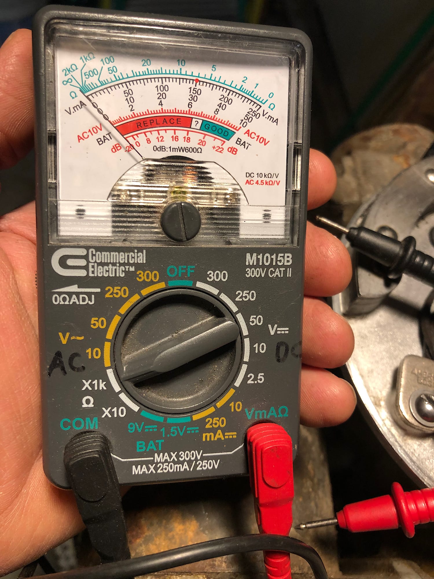
Here’s a pic of my meter setting:
 May 20, 2021 at 9:45 am #238657
Your meter is set correctly. Short your meter leads together to make sure the meter swings to zero.
A good coil reading should swing the meter to the right to around the number 5..020 gap is good. I would definitely change that old capacitor. They may check decent now but are notorious for failing when they get warm.
A coil can read poorly or open and still give spark for a time. If the wire in the secondary is broken and the gap of that break is very close the spark can jump that gap and still fire the ugs. What eventually happens is the wire break gap gets bigger and the coil stops firing.
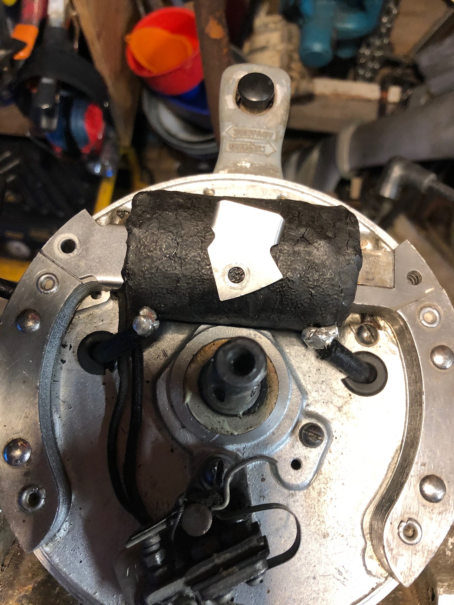
Where the coil heels attaches to the laminationsooks strange to me.May 20, 2021 at 11:52 am #238664There are little covers on the ends of the coil where they meet the laminations. They’re held on by that little screw. I will check my phone to see if I have a picture with the cover removed.
-
This reply was modified 4 years, 10 months ago by
-
This reply was modified 4 years, 10 months ago by
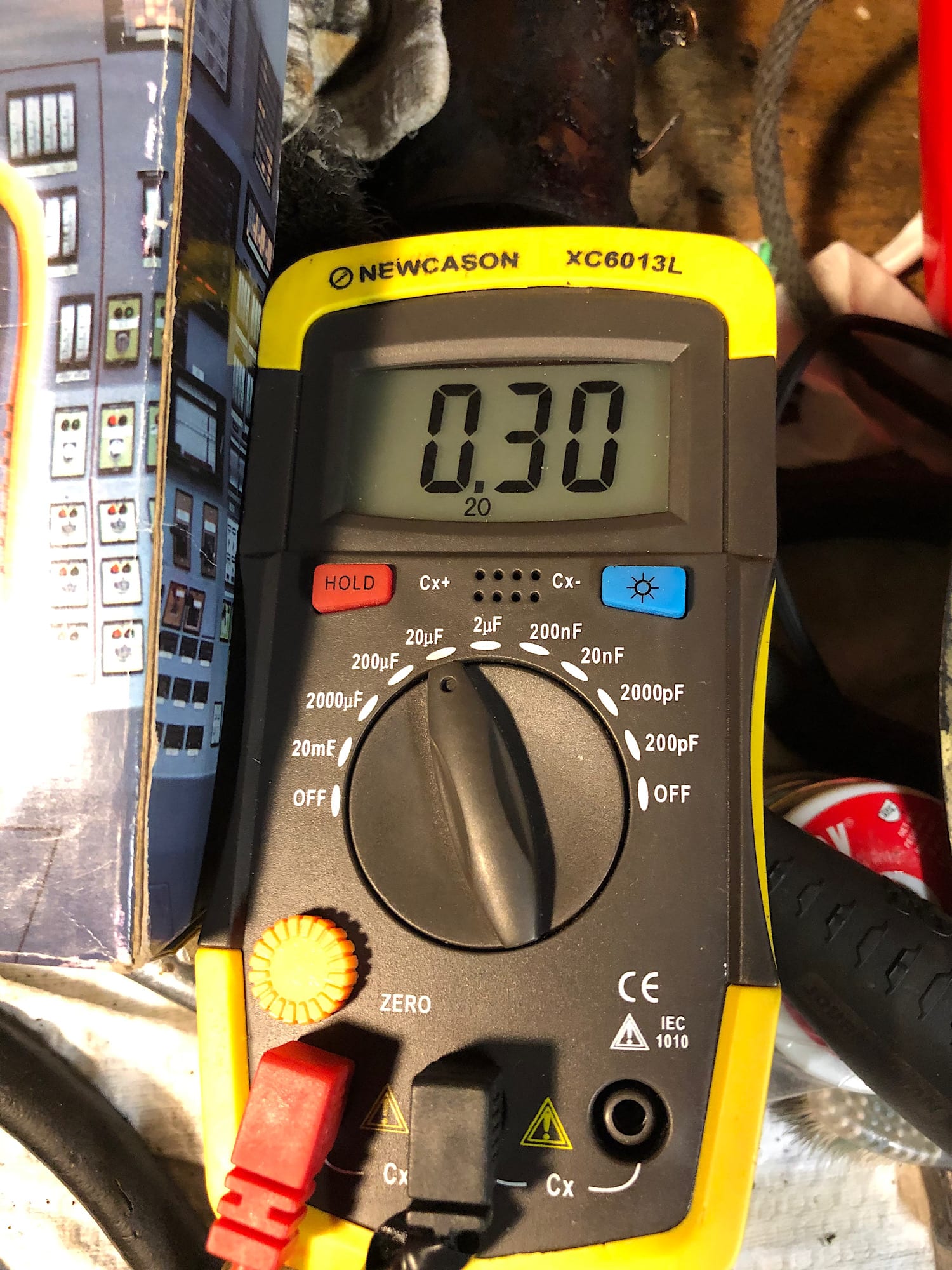
May 20, 2021 at 9:57 pm #238688Ok, here’s the reading I’m getting when testing the condenser. The scale says .30. What is that telling me?
By contrast, I have a new OMC condenser on hand and that one measures .21 on the scale.
-
This reply was modified 4 years, 10 months ago by
-
This reply was modified 4 years, 10 months ago by
-
This reply was modified 4 years, 10 months ago by
-
This reply was modified 4 years, 10 months ago by
-
This reply was modified 4 years, 10 months ago by
May 21, 2021 at 8:23 am #238702That is the MFD rating of the condenser.
Prepare to be boarded!
May 21, 2021 at 10:32 am #238708That is the MFD rating of the condenser.
Buc, does it appear adequate?
May 21, 2021 at 10:53 am #238709The 0.30 uF reading is fine, but it doesn’t tell the whole story. Magneto condenser testers function at a significant voltage (above 100 V) and measure the leakage. Very typical of a leaky condenser is seeing one or two sparks when you rotate the flywheel, then none after that. If you’re trying to start a motor, you might get one or two pops, which encourages you to keep trying. The WICO brass can condensers are notorious for this. Since you have a new one, try it and see if it makes a difference. Or get them both tested on a Stevens, Heathkit, or Merc-O-Tronic device, or even one of those simple ones with the neon light. As an aside, I recently went through a bin of condensers that had been saved by a friend. There were over 50 condensers. I tested them at 200 V with a Heathkit C-2. There were two good ones in the pile. One was a new OMC, the other was an original condenser from a Johnson A.
T
-
This reply was modified 4 years, 10 months ago by
-
AuthorPosts
- You must be logged in to reply to this topic.