Home › Forum › Ask A Member › Do I have the right pump?
- This topic has 35 replies, 8 voices, and was last updated 9 years, 6 months ago by
Don.
-
AuthorPosts
-
September 15, 2016 at 1:34 am #44051quote VinTin:I don’t know what other differences there are but one difference between the 1968 20hp and the 1969 25hp is the 25hp is exhaust tuned.
How do we distinguish? They both seem to use the same inner exhaust tube and exhaust housing assembly.
Also seems that they went to the fixed main jet in 1964 so not likely to be farther back than that.
September 15, 2016 at 3:42 am #44060Wish I saw this thread sooner. Let me offer some help since I work on around 50 of these units a year (18/20/25hp pre 1977).
Your gearcase is not a newer style gearcase. The prop shaft doesn’t have splines on it. In 1977, it switches to a splined prop shaft (correct me if I’m wrong). As mentioned, check your exhaust housing to see if there is an orifice to accomodate the driveshaft ‘spacer.’ These GREATLY improve water pumping action because they help shield the impeller housing from exhaust gases getting in.
These motors pump a ton of water, even prior to this update around 1970. You can even run one of those motors that are updated to take the driveshaft spacer without one and they still pump a lot of water, but I wouldn’t recommend it. If the impeller gets weaker, there is a much smaller margin of error. FrankR may be able to clarify, but I believe around 1973, a water restrictor was added under the powerhead on top of the exhaust housing to slow down water supply. They can run cold (and are not as good idlers) the closer to 1976 that you get.
As mentioned, you may have an odd combination impeller housing to the exhaust housing. You just have to look and see. If you have a motor with an exhaust housing indicating it should have a driveshaft ‘spacer,’ than get the correct impeller housing.
In terms of the 4 holes in the gearcase, all of these gearcases are drilled for 4 impeller housing screws, but may only accept 3. You’ll see the SS impeller plate only accomodates 3 holes too. The size of the screws changed from really skinny, fine thread to thicker standard thread at some point. I don’t remember when. I all I know is the older skinny, fine thread screws SUCK. They almost always get stuck, break, or the heads pop off. Trying to drill them out and retap, forget it. Just go 1 size bigger and update to better screws.
Now identifying what motor you have isn’t going to be easy if folks have been combining odds/ends motors. Keep in mind the difference between the 18/20 and a 25 is really the cylinder head (clearly different if you pull them), and the crank, manifold, rods, and internal porting of the block. Other than the cylinder head, these others things aren’t something you can casually identify. I guess if you pull the flywheel to service the magneto, you might get lucky and still have a P/N stamped on the taper. But that is rare. Your motor has a newer style carburetor, which I suspect is a 25hp carburetor. The older 18/20 carbs were used (I believe) up to 1970.
Here is a pic of the cylinder head differences on my website: http://runneroutboards.com/motor101/powerhead/powerhead.html#18-20_Differences
You can go by block color to a certain extent; keep in mind in the early 70’s johnson kept the 20hp line, evinrude the 18hp line. But both carried 25hp motors? Disregard identifying based on anti-ventilation plate or shift levers. If you don’t have the ID tag, or have a core plug, it’s likely best guess. You’ll know once you go full throttle because there is a marked difference between an 18/20 and a 25 at the top end.
For what it’s worth I have 3 or 4 of these frankenmotors waiting to be fixed this winter where I’m going to have to figure out what they are using the same detective work. And the only difference between a 18 and 20 is the leaf plates. It really gets fun when some knucklehead decides to try and convert an 18/20 to a 25 (Can’t be done!) and starts strapping components of a dead 25 to an 18/20. When you see your compression gauge read 185-200PSI, that means they put the wrong cylinder head on a 18/20! I wouldn’t want to be around that motor when they run it!
September 15, 2016 at 5:23 am #44063quote johnyrude200:Wish I saw this thread sooner. Let me offer some help since I work on around 50 of these units a year (18/20/25hp pre 1977).Your gearcase is not a newer style gearcase. The prop shaft doesn’t have splines on it. In 1977, it switches to a splined prop shaft (correct me if I’m wrong). As mentioned, check your exhaust housing to see if there is an orifice to accomodate the driveshaft ‘spacer.’ These GREATLY improve water pumping action because they help shield the impeller housing from exhaust gases getting in.
Yes, it takes a spacer. It was crudely cut off, I think because the pump housing was one it couldn’t spigot into.
These motors pump a ton of water, even prior to this update around 1970. You can even run one of those motors that are updated to take the driveshaft spacer without one and they still pump a lot of water, but I wouldn’t recommend it. If the impeller gets weaker, there is a much smaller margin of error. FrankR may be able to clarify, but I believe around 1973, a water restrictor was added under the powerhead on top of the exhaust housing to slow down water supply. They can run cold (and are not as good idlers) the closer to 1976 that you get.
As mentioned, you may have an odd combination impeller housing to the exhaust housing. You just have to look and see. If you have a motor with an exhaust housing indicating it should have a driveshaft ‘spacer,’ than get the correct impeller housing.
In terms of the 4 holes in the gearcase, all of these gearcases are drilled for 4 impeller housing screws, but may only accept 3. You’ll see the SS impeller plate only accomodates 3 holes too.
True.
The size of the screws changed from really skinny, fine thread to thicker standard thread at some point. I don’t remember when. I all I know is the older skinny, fine thread screws SUCK. They almost always get stuck, break, or the heads pop off. Trying to drill them out and retap, forget it. Just go 1 size bigger and update to better screws.
It seems the screws on this are #8 by 32 and most of the motors I’ve seen are #10 by 24. The plastic pumps seem to use 1/4 by 20 screws. This seem right? I can drill and retap for #10 by 24.
Now identifying what motor you have isn’t going to be easy if folks have been combining odds/ends motors. Keep in mind the difference between the 18/20 and a 25 is really the cylinder head (clearly different if you pull them), and the crank, manifold, rods, and internal porting of the block. Other than the cylinder head, these others things aren’t something you can casually identify. I guess if you pull the flywheel to service the magneto, you might get lucky and still have a P/N stamped on the taper. But that is rare. Your motor has a newer style carburetor, which I suspect is a 25hp carburetor. The older 18/20 carbs were used (I believe) up to 1970.
Here is a pic of the cylinder head differences on my website: http://runneroutboards.com/motor101/powerhead/powerhead.html#18-20_Differences
So I really need to pull the head if I want to know?
Very interesting site!
You can go by block color to a certain extent; keep in mind in the early 70’s johnson kept the 20hp line, evinrude the 18hp line. But both carried 25hp motors? Disregard identifying based on anti-ventilation plate or shift levers. If you don’t have the ID tag, or have a core plug, it’s likely best guess. You’ll know once you go full throttle because there is a marked difference between an 18/20 and a 25 at the top end.
For what it’s worth I have 3 or 4 of these frankenmotors waiting to be fixed this winter where I’m going to have to figure out what they are using the same detective work. And the only difference between a 18 and 20 is the leaf plates. It really gets fun when some knucklehead decides to try and convert an 18/20 to a 25 (Can’t be done!) and starts strapping components of a dead 25 to an 18/20. When you see your compression gauge read 185-200PSI, that means they put the wrong cylinder head on a 18/20! I wouldn’t want to be around that motor when they run it!
September 15, 2016 at 3:59 pm #44076Comparing with the pics on your site, I’d say this is the 25 hp head. Agreed? There is a little scoring of the bore. (Sorry pic out of focus). Think I can run it without a teardown?
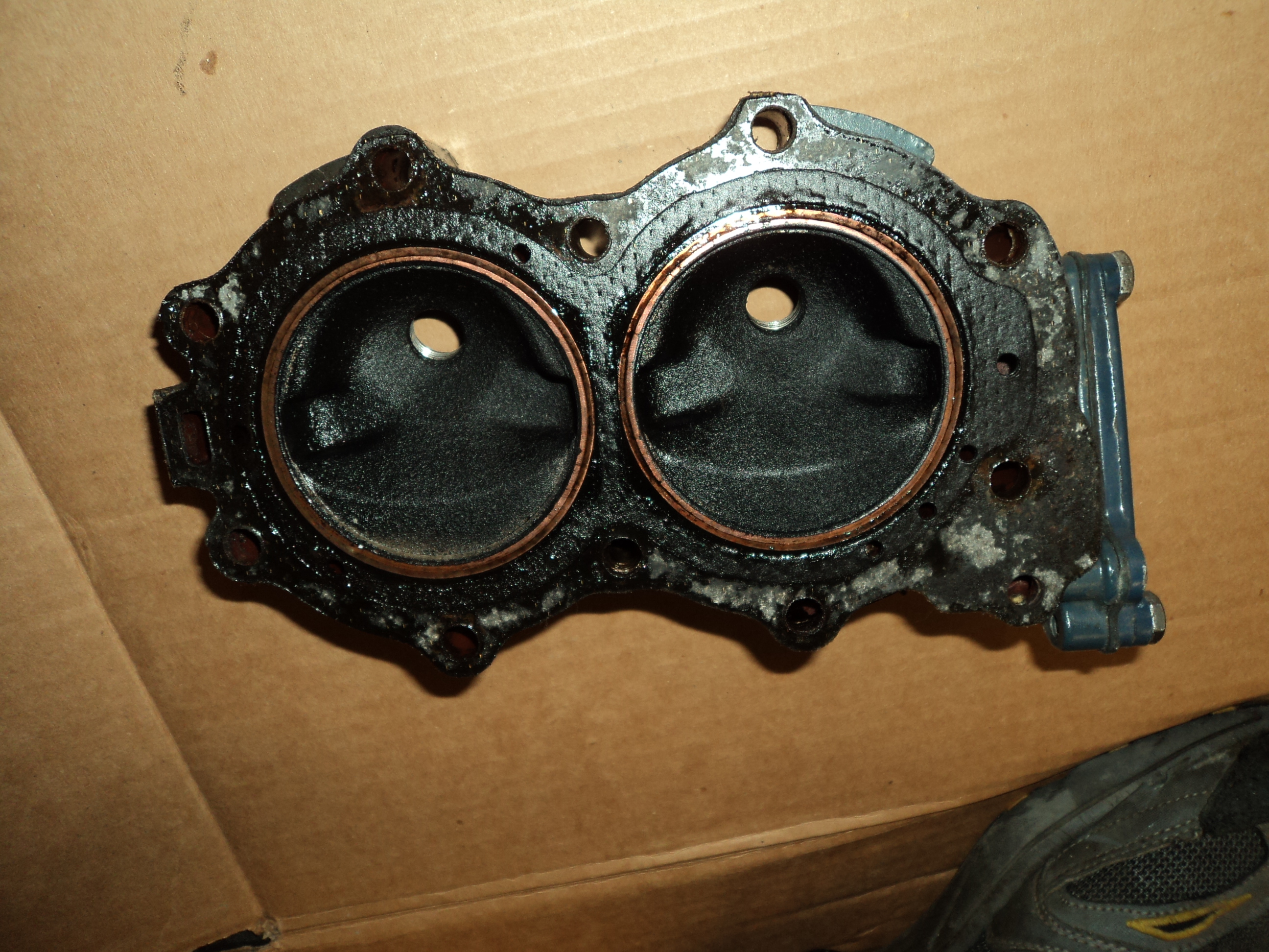
So, ’69 being the first year for 25s, I feel this is a ’69 or later. It appears from looking on shop.evinrude that ’72 was the last year for the traditional magneto, at least on the 25s. So I’m thinking 69, 70, 71, or 72. Any way to pin it down closer?
am
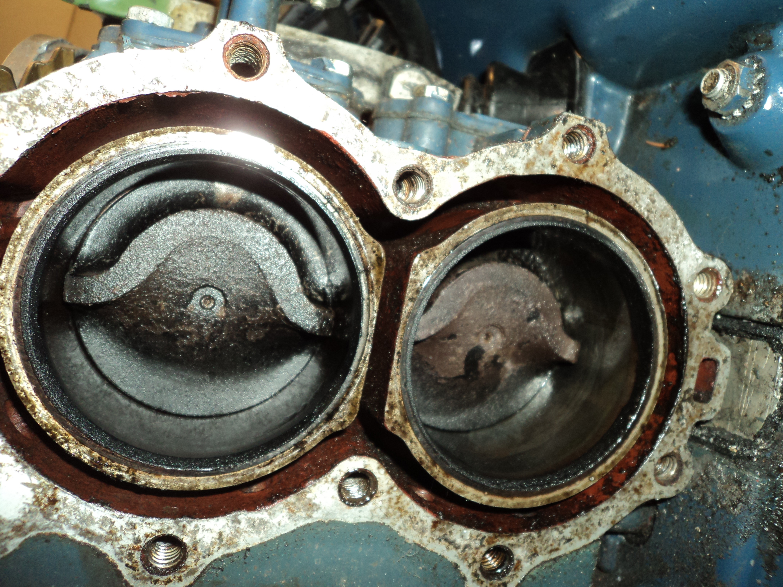
September 15, 2016 at 5:28 pm #44084It’s probably between the years ’69-72. After that the low-tension magneto was used on these. But there are people who revert the 73-76 models back to the universal magneto because they are generally easier to deal with. Your cylinder head doesn’t have the bosses for the external coils, so unless someone took the trouble to switch cylinder heads, you can probably bet it’s original to the block. Do the colors match? Did the head gasket seem ‘married’ to both the cylinders and head? If yes, that is just more evidence that it’s original to the block. I doubt anyone who go to the trouble of switching out the crank and manifold, along with the carb. Unless you have someone spending a winter on it as a hobby (long shot).
In terms of the impeller housing screws, I can’t comment on which ones you should use without seeing the housing, but of course you won’t be able to use the smaller diameter ones with a housing calling for the larger ones, without using some very small SS washers to secure the housing to the gearcase. If the threads are boogered up, well it’s not hard to retap the gearcase orifices being that it’s aluminum. You can get away with 2 out of the 3 screws so long as they are opposite of each other. If they are next to each other I would consider that iffy in terms of exhaust getting in.
And make sure that little relief hole in where the water tube goes into the housing is clear (you have to remove the rubber water tube grommet to see through). Those 2 O-rings on the spacer need to be new, soft, and snug, otherwise it will cause water flow to be affected by the exhaust pulses of the motors.
When you move up to the ’77-thru motors, if those O-rings are PERFECT, it will literally shut the water off completely like a faucet! Those 32 C.I. motors breath a lot more than the original 22 C.I. ones!
Check your compression numbers. They’ll run at anything above 90, but 120+ is more desirable. A really good condition unit will show 150PSI. I have seen extraordinarily low-hour/well-maintained units hit 165PSI on my gauge for the 25hp variety. The 18/20’s, best numbers I’ve seen is 135PSI. Note these are cold/wet measurements. After running, the numbers will change.
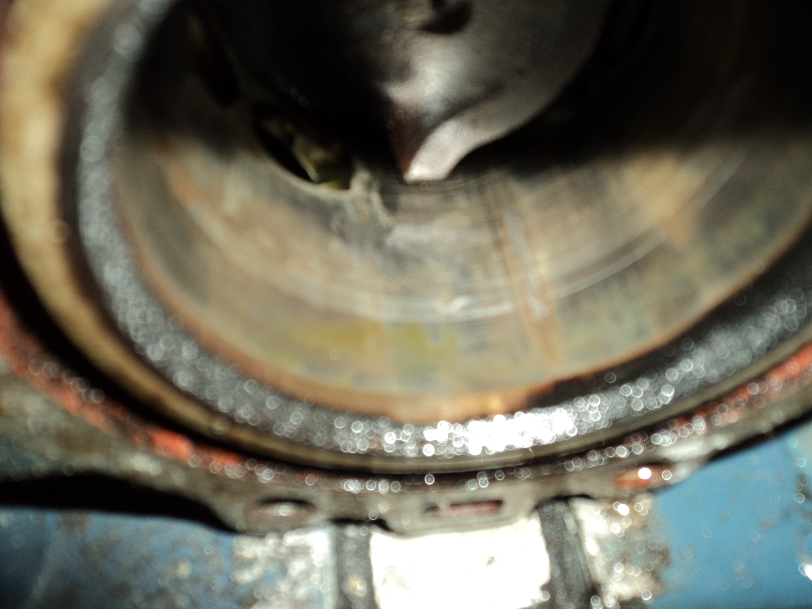
September 16, 2016 at 12:39 am #44121Well, that paint appears original, and the color tells me the engine is an 1969 or 1970 Evinrude. 71 and 72 models had a deeper darker blue color. It is not real uncommon for the engines to pick up a few scratches/scores throughout the years, you don’t see any aluminum on the cylinder walls do you? I can’t really see the walls very well in your pictures… Why is it that you pulled the cylinder head anyway?
Now that you have pulled the head, I would use some fine emery and scuff up those cylinder walls to take the glaze off. I know, seems pretty darn crude, but we are not dealing with a nascar race engine here. The engine looks to be a fresh water engine, no signs of salt/corrosion in there!
Clean up the mating surfaces, replace the head gasket and you may as well do the thermostat while you are at it…
I thought you said the midsection was white???
I remember you saying you paid $60 for this engine, I’m trying to keep you from getting in too deep on this project. Find the correct impeller housing and SS impeller plate, replace the impeller, use the original screws (don’t drill the holes out needlessly), and replace the impeller housing spacer/orings. I know the three screw set up seems flimsy, but it was been working successfully on these engines for many years! That being said, take some time to make sure the SS plate is mating properly to the housing, then use the typeM/347 sealer to ensure it is sealed properly. Don’t put any sealer between the impeller housing as SS plate, that will end up getting shmeared around on the impeller and SS plate.
I think we have "over analyzed" this project, let’s put it together and see how she runs! -
AuthorPosts
- You must be logged in to reply to this topic.