Home › Forum › Ask A Member › Johnson 1949 HD 25 No Spark
- This topic has 34 replies, 8 voices, and was last updated 1 week, 3 days ago by
TiIngot.
-
AuthorPosts
-
December 28, 2025 at 8:12 pm #302719
About 30 years ago this 1949 was given to me by my neighbor. I tried using it on my side mounted canoe but with me and the motor in the rear it was stern heavy. The one time I had my neighbors 13-year-old son in the front it ran about 45 minutes up the Mahoning river and started really running poor. We shut it off and paddled back down stream. Thinking it was overheating I replaced the rubber water pump but never got it running again. The starter rope broke, and it sat in the shed for over two decades.
Now I am trying to get it running and give it back to my neighbors now 43-year-old son. It was stored with no fuel in the tank and the carb drained. First, I repaired the recoil rope and found no spark at either plug. Next the compression test only shows 52 psi in either cylinder. Last what could cause loss of spark in both plugs? It went from running to not running. Thus, I have a lot of questions, and I will number them. 1.) I have spent a week troubleshooting the no spark issue but before I go on this path, am I wasting my time with only 52 psi compression? 2.) Can something be used to pour into the plug holes to soak the pistons that may release stuck rings thus increasing compression?
On to the no spark issue. 3.) When it was running a couple decades ago, was it possible it was running on only one cylinder? I ask because I cannot figure out what common denominator that would kill both circuits except the stop switch. I checked; the stop switch is not shorted to ground except when the magneto is in the stop position. 4.) What is the correct MFD range for the condensers? The following are diagnostic actions I have performed to date.
a. Both Champion J8 plugs checked ok using an ohm meter continuity check.
b. Substituted second plugs for test purposes.
c. My spark plug test light is working properly.
d. Coil shoe gaps on each magneto set at .012 all three shoes.
e. Continuity of each primary and secondary coils on each magneto checked ok.
f. Continuity of each spark plug wire checked ok.
g. Both point sets removed, cleaned points filed clean and installed to .020 gap.
h. Stop switch has no continuity to ground at any magneto setting except when it is in the stop position.
i. Both condensers tested, one at 206 mfd, other at 246 mfd. Are these readings ok?
I’m stumped by an outboard as old as I am. I should know how plugs, points, condensers and magneto’s work at my age. Maybe it is old age senior moments acting on he.
TiIngot (Titanium Ingot Melt Shop Manager)
Retired titanium melt shop manager. (Think about me next time you fly in a window seat and look at the engines spinning below the wings!)
December 28, 2025 at 8:25 pm #302720Are the flywheel magnets still strong?
You could also try checking the gap on each spark plug.
Are you pulling it over with a rope or turning the flywheel by hand because it might not spark if being spun over too slow, which could be the case if you aren’t using a rope.
I wouldn’t worry about the compression for now. Just don’t feed the motor any less oil than 16/1.
December 28, 2025 at 10:33 pm #302727.
A "Boathouse Repair" is one thats done without having tools or the skills to do it properly.
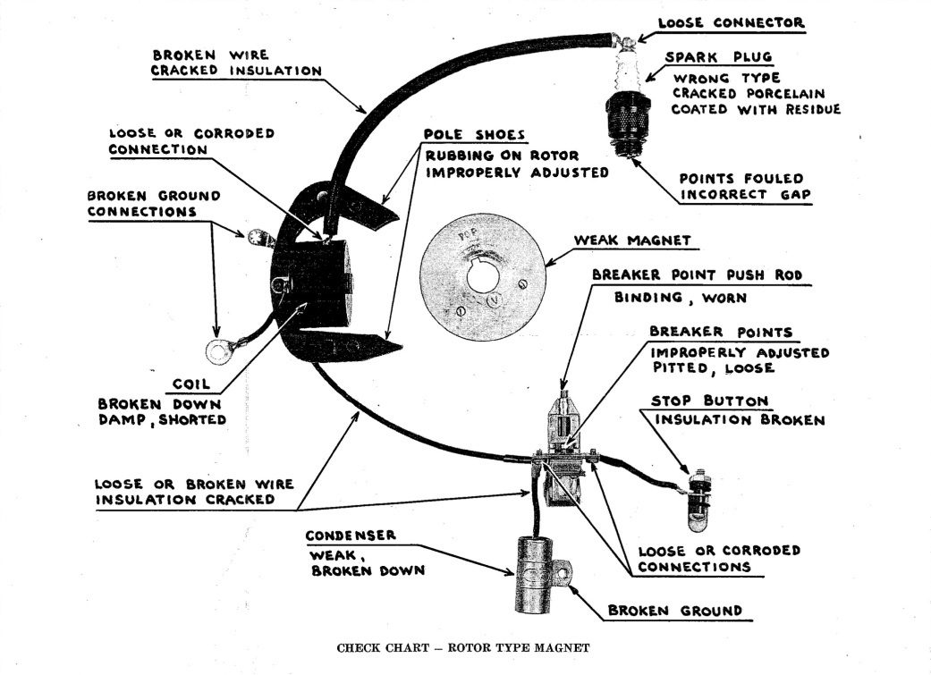
December 29, 2025 at 7:13 am #302730The ignition system for the “H” series motors is a little different than the later universal ignition shown above. This ignition features “horseshoe” coils that have the coil shoes facing inward toward the crankshaft instead of outward toward the flywheel. The magnets are imbedded in a rotor that spins with the crankshaft.
Most of the time, the condensers and coils survive on these motors, and it would be unusual for both ignitions to go dead. Tubs mentioned dirty oxidized points as a possible problem and that’s a very likely cause, but you have cleaned and reset the points.
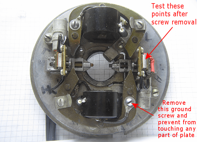
One thing to check is that the very tiny insulators in the points that prevent the tiny screws from shorting out are intact. If these easily lost insulators are missing or degraded, the points cannot break electrically and there will be no spark. Points can also be tested with an ohmmeter both opened and closed.
The kill switch also has insulating washers that alternate with conducting parts.
A helpful website for H and T model Johnsons: pochefamily.org
The 52 PSI compression is low for this model. These rotary valve motors prefer 70+ PSI for a good idle. The compression will improve some with use if you can get it running.
Improvise-Adapt-Overcome
December 29, 2025 at 11:26 am #302736Three very quick replies. Thanks to all. Based on all the input so far, I am focusing on the points ……again. (I hate those little screws and washers with a passion! They bounce really far when hitting the floor. Finally put a catch box under the outboard stand.)
To completely isolate the points, both sets are removed and back on the bench. A piece of thin cardboard is inserted between the points on each. On both set of points, with the cardboard inserted, I have no continuity between the aluminum ground and the brass.
However, removing the cardboard on both sets which closes the points, I have continuity between ground and the brass on one and not the other. I heavily cleaned both sets of points with my points file again and now both sets of points have continuity when closed and no continuity when opened. (I previously tried to clean the points without removing them.)
If this works after assembly, I am expecting one cylinder to spark and not the other. I will use my electric drill to spin the flywheel also. To be continued
Thank you again.
Retired titanium melt shop manager. (Think about me next time you fly in a window seat and look at the engines spinning below the wings!)
December 29, 2025 at 6:06 pm #302752I completely removed both sets of points and inserted a thin piece of cardboard between them. Both sets had open circuits with cardboard inserted. However, removing the cardboard and with the points each closed, one set still had an open circuit. I used my points file and heavily cleaned the points and now both sets have continuity when closed and no continuity when opened with cardboard inserted. (Before I tried to clean them while installed.)
Went to O’Reilly’s and bought two new J8C plugs and a new plug spark tester. They did not have a capacitor. Point gaps set at .020. Magneto gaps set at .012. Using electric drill to spin the flywheel and still no spark in top or bottom plugs.
I am back to looking at the stop switch/circuit. The underside of the stop switch is not easily assessable without taking the entire magneto assembly off the motor which I do not want to get into. I have no clue what insulation is within or around the screw bolt that is in the so-called switch. However, the nut on the top side of the stop switch is accessible. Under this nut is two wires coming from each of the points and a waxy residue, like bees’ wax. Both wires are unscrewed from their points to isolate them.
Both wires from the points to the switch have continuity, not broken. With the magneto in the start position, both wires have open circuit to ground. However, with the magneto at the stop position only the bottom short wire from the near points is grounded. The longer wire going to the opposite points still has an open circuit. Under the stop switch nut it looks like there may be an insulator between the two points ground wire and it looks like it may be the bees’ wax like stuff.
Anyone know what the stop switch assembly looks like or know of a reference on the internet that may describe the switch?
For testing, if I totally remove the stop switch from the ignition circuit would it change the operation or just prevent the ability to ground the points to stop the engine if running?
Still puzzled.
Retired titanium melt shop manager. (Think about me next time you fly in a window seat and look at the engines spinning below the wings!)
December 29, 2025 at 9:41 pm #302777It’s easy to pull the magneto off these in most cases,
as long as the rotating magnet comes off okay.
I did one today, and just carefully pried the magneto
up with two screwdrivers.
Then, it’s just a clamp / tension bolt under the mag plate
to loosen, and it pulls right up.
Prepare to be boarded!
December 30, 2025 at 4:26 pm #302811Thanks for the picture and the reply.
I have one question about the single wire going from each point set to the stop switch. I am assuming the only purpose for this wire from the points to the stop switch is to ground the points to turn the outboard off when the magneto is in the stop position. For diagnostic purposes, if I disconnect this wire at both points and tape the end, it will have no effect when I reassemble the flywheel, set the magneto to start and spin the motor looking for spark. Am I correct?
Retired titanium melt shop manager. (Think about me next time you fly in a window seat and look at the engines spinning below the wings!)
December 30, 2025 at 5:52 pm #302816Yes, you are correct about the wires. A continuity meter is you friend here if you’re looking
for a grounded wire, or bad insulator, etc.Prepare to be boarded!
December 30, 2025 at 6:06 pm #302817 -
AuthorPosts
- You must be logged in to reply to this topic.