Home › Forum › Ask A Member › Johnson 1949 HD 25 No Spark
- This topic has 33 replies, 8 voices, and was last updated 1 month ago by
TiIngot.
-
AuthorPosts
-
January 7, 2026 at 10:22 pm #303142
I cannot post pics here because my iPhone resolution makes them over 2 MB. I have not removed the kill switch because I think the insulators within it are falling apart. On the top side under the kill switch nut where the two condenser wires go mine looks like, top to bottom, the nut on top, condenser wire, insulator, second condenser wire, insulator then magneto plate. The two condenser wires have an insulator between them so in the stop position only one wire goes to ground. My logic thinks insulator on bottom, then both wires next, then the top insulator and the nut last.
Am I correct?
Sorry, but I can’t follow what you’re saying and get a clean picture
in my mind.
I posted this photo before on the order of the parts in the kill switch post.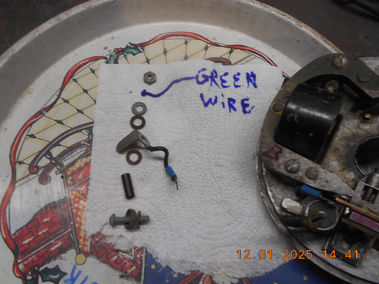
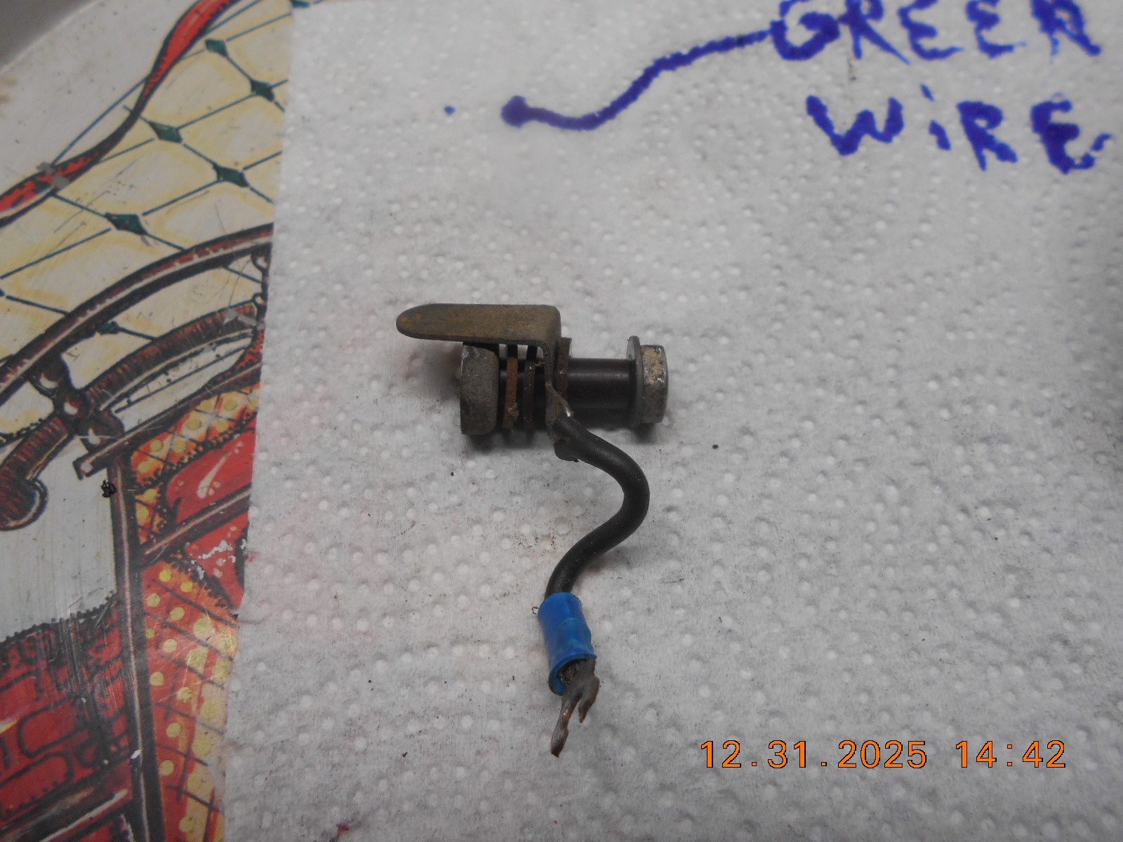
The “kill” wires on mine basically run in between the two sets
of points, attached to the brass bar. In between is the insulated
kill switch post, and when activated, grounds the two ignition
systems together, killing the engine.Prepare to be boarded!
January 8, 2026 at 1:38 am #303146fwiw..
don’t mean to simplify but why not solve one problem at a time.
remove all connection to the stop circuit(s) & just join the wires from condenser to points and get the thing sparking properly
if you get it going you can kill it by choking it
reinstall the stop switches to/via the condenser junction (switches) which should remain ungrounded until physically activated to the join ground on the engine frame to kill the engine
if they are mecanically defective find spares and replace or MC giver a kill circuit to ground the condenser/coil assemblies
like done in the 50s engines
Joining AOMCI has priviledges 🙂
January 8, 2026 at 6:20 am #303149The two ground wires from the points require an insulating washer between them. I believe the insulating washers are made of bakelite, but nylon washers work well as a substitute. As Buccaneer mentioned, the idea behind the kill switch is to short the points to each other.
The entire kill switch assembly is insulated from ground until contact is made by the thin springy 90-degree contact with bell shaped contact washer at the bottom of the stop switch.
In 1958 OMC started using a “push to stop” kill switch for the larger horsepower motors. This was a different kind of switch, but it worked in a similar fashion by keeping the two wires insulated until the button was pressed, shorting one set of points to the other.
Improvise-Adapt-Overcome
January 30, 2026 at 9:34 pm #304126I apologize to those that have provided guidance to me. I’m still at it though. It has been three weeks of “issues” that pulled me off the HD 25 project. Here my current status. I found two new NOS condensers for $9.99 each on eBay and purchased them. While waiting for their arrival I found the complete magneto/ignition assembly for $14.99 !!! on eBay too. Complete meaning the entire ignition plate with two magneto’s, two points sets, two condensers, stop switch …. everything, The Holy Grail !!!
Well, USPS lost the shipment. It finally arrived two weeks late. Now I have an assembly that I can compare ohm, continuity and capacitance readings with. On my original ignition system, I only found one bad magneto. Everything on the purchased unit checked out OK so I removed and cleaned both point sets and swapped out the entire ignition assembly and rechecked all the magneto and point gaps.
I am using my DeWalt battery drill to spin the engine and I now have good spark on the bottom cylinder and intermittent or weak spark on the top cylinder. The next move is to pull the top points and swap them out with one from the original set.
Again s**t happens. 4 driveways + 15″ of snow + plus a 77-year-old back = I can hardly walk. To be continued.
Thanks again.
Retired titanium melt shop manager. (Think about me next time you fly in a window seat and look at the engines spinning below the wings!)
-
AuthorPosts
- You must be logged in to reply to this topic.