Home › Forum › Ask A Member › Opposed Twin Magneto Question
- This topic has 6 replies, 5 voices, and was last updated 9 years, 2 months ago by
garry-in-michigan.
-
AuthorPosts
-
January 6, 2017 at 1:29 pm #6050
I am getting the magneto cleaned up on the Johnson A that I started a project thread about. Either something is wrong, or I don’t fully understand the operation of the magneto setup….likely the latter.
The coil shows 9.2K Ohm from plug lead to plug lead with the new wires on.
The primary winding shows 4 Ohm from the lead going to the points, to the ground on the laminates.
The kill button work properly.
The points make good contact and the two halves are insulated from each other.
Waiting for some Vishay Caps in the mail to replace the condenser.What happens in this system when the points break?
The circuit of the of the secondary winding would become open, and the lead side is connected to the condenser. Is this what causes the induction of the high voltage in the secondary winding?
Lots of info on the universal type mags, just trying to fully understand the opposed type.January 6, 2017 at 1:36 pm #50438The opposed type is similar to the universal mag, but instead of grounding one end of the secondary, it goes to the other spark plug.
In the universal mag, there are three wires: The high tension lead (secondary), the black ground wire, and the green wire to the points. The high tension lead is one side of the secondary winding. The black ground wire is the ground for one side of the primary winding AND the other side of the secondary winding. The green wire is the other side of the primary winding.
So if you research the operation of the universal mag, remember that the primary and secondary windings are both grounded together. In the early Johnson style opposed twin coils, the primary and secondary windings are not connected.
Hope this helps.
T
January 6, 2017 at 3:47 pm #50446Anonymous
Off the top of my head:
Direct current induces a magnetic field in a coil,
but a CHANGE in magnetic field is needed to induce a current
(a magnet just sitting next to a coil doesn’t make current).The magnet moving past the heels of the core induces a current in the primary
(with a three-heeled coil, the flow of magnetic flux is reversed as the magnet passes
the center heel, which is a LARGE change in the magnetic flux).The current in the primary builds a secondary magnetic field in the iron core.
opening the points interrupts the current in the primary,
which causes the secondary field in the core to collapse
which induces a current in the secondary winding of the coil.The condenser absorbs current that would have caused a spark to jump the open points.
The stored energy in the condenser then discharges into the primary windings,
inducing a magnetic field in the core, until the condenser empties, then the primary current collapses, the magnetic field in the core collapses, which induces a new current in the primary windings, which recharges the condenser, rinse, repeat (getting smaller each time). All of this may extend the spark.January 6, 2017 at 4:49 pm #50451Thank you.
I think that I now understand it correctly. When the points break, they open the circuit of the primary winding and cause the current being generated to be absorbed by the condenser.This coil only has 3 wires, the primary lead to the points, and the two secondaries (plug wires). There is a small copper stub out of the coil body that is clamped in between the laminates. I am assuming that this is the other end of the primary winding that is always grounded.
Adam
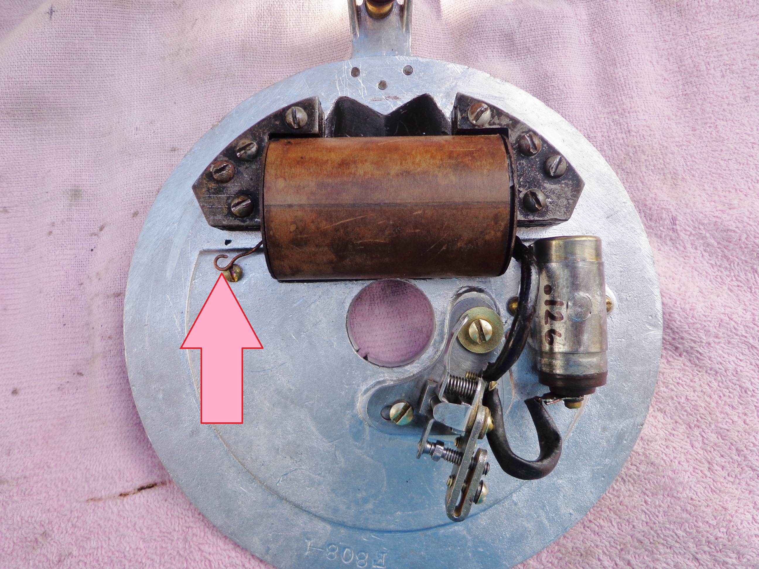
January 6, 2017 at 6:51 pm #50472Your A mag should look like this one. One primary circuit lead goes to the points and the other end of the winding goes to ground. It’s undone in this photo.
Attachments:
 January 6, 2017 at 9:36 pm #50484
That’s what I have. The lead indicated by the arrow is sandwiched into the laminates. The Condenser lead has its own terminal on the points and the coil lead shares a terminal with the kill lead.
January 7, 2017 at 1:55 am #50509It is easy to understand the primary circuit, but many are confused by the high voltage secondary. Since each end of the coil goes to a spark plug (insuring they both fire at the same time) the only way to complete the circuit is if both plugs are grounded to the block. Obviously if one wire is grounded the other plug will then get twice the voltage, but the grounded side will not fire its spark plug. So the way to ensure that the secondary is properly grounded is to be sure both plugs are firmly screwed into there proper holes. . . 😀


-
AuthorPosts
- You must be logged in to reply to this topic.