Home › Forum › Ask A Member › PO-15 Kill Switch Wiring
- This topic has 9 replies, 5 voices, and was last updated 9 years, 3 months ago by
 Buccaneer.
-
AuthorPosts
-
December 10, 2016 at 11:08 pm #5871
I’ve read the old threads on PO-15 wiring for the kill switch.
I’m not a Johnson engineer, nor an electrical genius, but
I see no need for three wires in the tiller handle.
Keep in mind I’m using a modern push button two pole
switch, which I presume the original was as well?
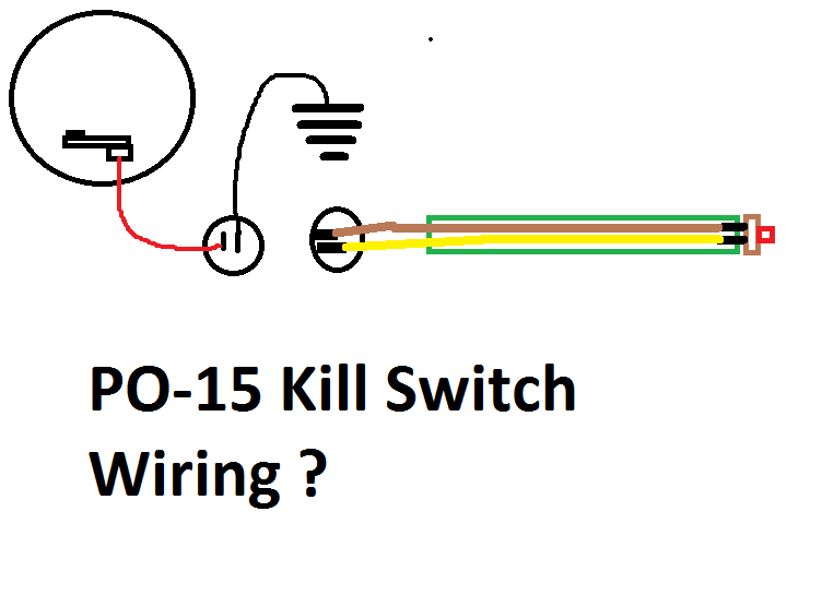
On my diagram below, I see no reason it would not
work, regardless of how I plugged in the connector.
I think I’d attach the "female" plug to the mag side
wiring to prevent the magneto grounding out, should
the connector come unplugged while running, as
someone mentioned in the old threads.Will my wiring plans work okay?
If so, what was Johnson thinking with the
convoluted three wires in the tiller handle?
Thanks!
Attachments:
Prepare to be boarded!
December 11, 2016 at 3:05 am #48983George explains the third wire good in this thread from a year ago.
viewtopic.php?f=2&t=4660&p=24091&hilit=PO+15+wiring#p24091
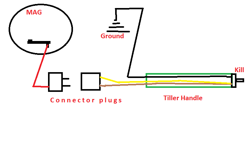
December 11, 2016 at 2:28 pm #48997I’ve read, and re-read the old threads. In doing so, the only
visualization I can get in my head is the wiring diagram
must be as in the diagram below.
So my question remains.
Is the original Johnson set-up with three wires in the tiller
handle "better" for some reason, that what I drew out in
the previous diagram?
Thanks.
Attachments:
Prepare to be boarded!
December 11, 2016 at 2:33 pm #48998better….? whatever works should be fine
Joining AOMCI has priviledges 🙂
December 11, 2016 at 2:53 pm #49000After walking the dog in the brisk winter wonderland,
pumping fresh blood to my brain, the only benefit I see
in Johnson’s set-up vs. my first drawing is that the ground wire would
not have to go through the plug-in connector, lessening the
chance of a bad ground.
I’d hate a "bad ground" when the PO is running out of control ! 🙂Prepare to be boarded!
December 11, 2016 at 6:46 pm #49015The third wire is so you can connect the plug either way. It wasn’t polarized as they are today with one large and one small terminal. Your two wire circuit in the first diagram should work and that’s exactly what I’ll be doing in the spring.
Why not jump both terminals inside the male and female ends so it won’t be critical which way they are connected if you are using the original style plugs and a separate ground wire?
December 11, 2016 at 10:35 pm #49026Not necessarily better, but certainly fool proof with the old non-polarized plugs. The way it could be better is to run a wire from the magneto base plate (ground) to the tiller ground. . . 😆

 December 12, 2016 at 1:39 am #49047
Mumbles, that would make sense to jumper at the tiller handle wire plug,
then one could have the same set up and only run two wires in the tiller
handle. Good idea, thanks!
Garry, another good idea as long as the ground wire is free to
move when the mag plate does.
Thanks!Prepare to be boarded!
December 13, 2016 at 12:42 pm #49110Someting else about the old way of wiring and that is "yes"–it could accidentally ground out if the male plug coming off the mag plate touched ground. But consider this,–if you were out running and the kill button malfunctioned, you could unplug the connectors and hold the male plug to ground to stop the motor…
December 13, 2016 at 1:44 pm #49113Good point George!
Better than breaking the spark plugs off!Prepare to be boarded!
-
AuthorPosts
- You must be logged in to reply to this topic.