Home › Forum › Ask A Member › Vintage 10 amp regulator connections
- This topic has 10 replies, 4 voices, and was last updated 9 years, 1 month ago by
 frankr.
-
AuthorPosts
-
January 31, 2017 at 2:00 am #6236
How is the red battery wire connected in the junction box?
There are five wires from the regulator.
One Red goes to the auxiliary hook up
Block Hooks ups…
Blue to the field
Yellow to the Armature
Black to the groundHow is the other red connected?…it has a female spade connection.
Thank you,
Mas
January 31, 2017 at 9:40 am #52198Actually, those red wires are supposed to be brown. Comes from the "Bat" terminal on the regulator to the strip just below the 20A fuseholder. That strip is just a connector. From the other end of that connector strip, another brown wire goes forward to the "Gen" side of the ammeter. From the "Bat side of the ammeter, a green wire goes back to the junction box and connects to the big terminal on the starter solenoid—the one that the battery + cable is on. So, following the electrical flow, the regulator output goes to the ammeter for measurement, then color changes to green going back to meet the + battery cable at the solenoid. If you balk at using an ammeter, you can just eliminate the wires going forward and back and instead just connect the brown to the + cable side of the solenoid. But you still need the green wire to feed the ignition switch (or choke/start buttons)
The 20A fuseholder is common with the connector strip just below it, and serves to fuse the auxillary power take-off on the bottom of the junction box cover.
January 31, 2017 at 2:15 pm #52204Thank you…that clears it up a lot. Question…I’ll be using push button start/choke (1957), does it matter what terminals on the switches are used for the connections…there doesn’t seem to be any markings on the switches??
Thank you
Mas
January 31, 2017 at 3:13 pm #52206Non-polorized (doesn’t matter)
February 1, 2017 at 5:01 am #52238Thanks Frank!
February 2, 2017 at 1:13 am #52270I’ve got two vintage Prestolite regulators…both 10 amp. They look identical, except one has additional wires for the PTO and and a ground wire…might there be differences inside that would not allow the PTO for the three wire model?
Thank you for your insight.
Mas
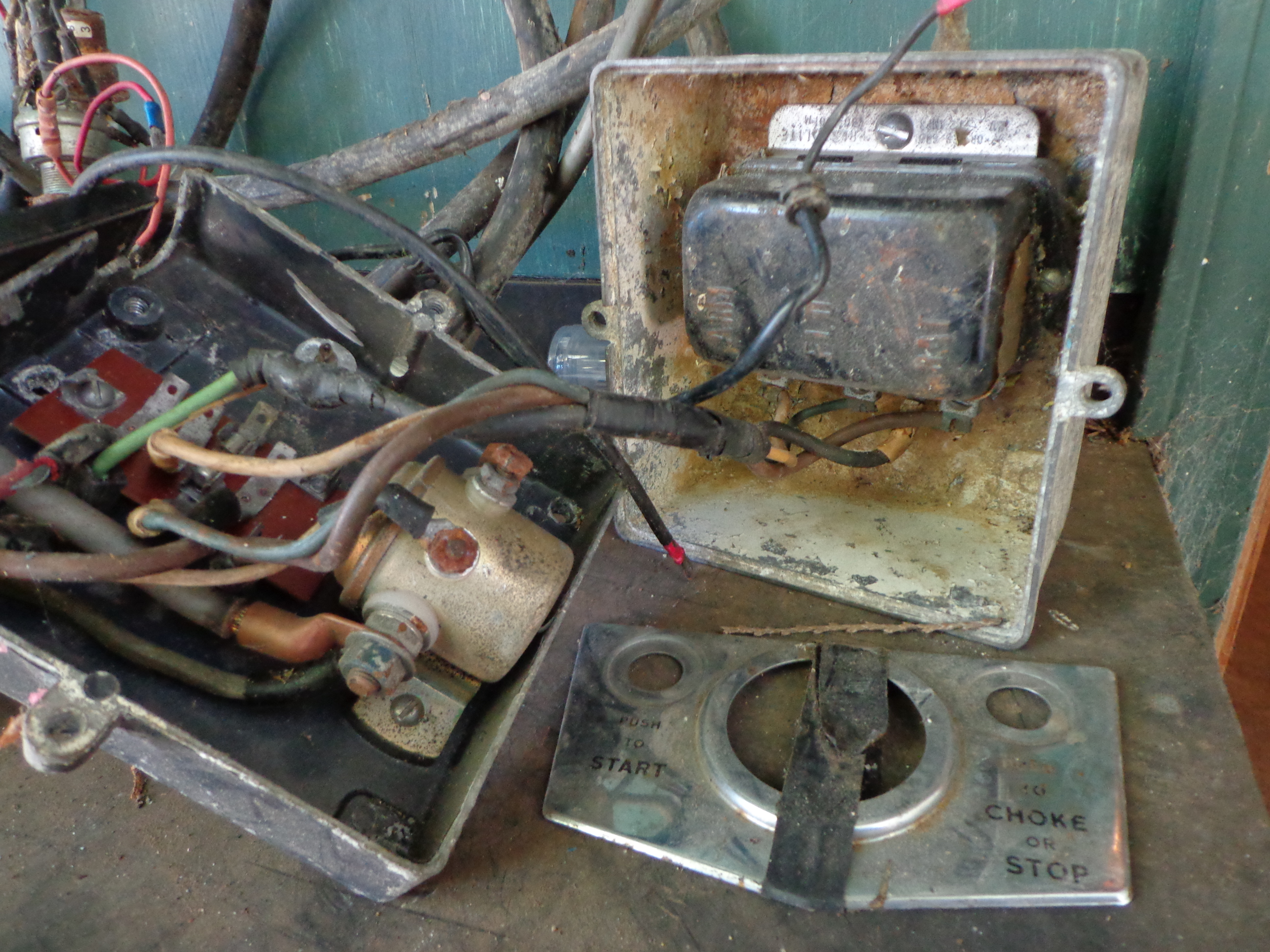
February 2, 2017 at 3:03 am #52274I came across a few electrical boxes today and took a photo of this one. Not sure if it helps or not.
Attachments:
 February 2, 2017 at 6:27 am #52277
I remember them being a lot cleaner than that. . . 😆

 February 2, 2017 at 10:32 am #52281quote Mas:I’ve got two vintage Prestolite regulators…both 10 amp. They look identical, except one has additional wires for the PTO and and a ground wire…might there be differences inside that would not allow the PTO for the three wire model?
Thank you for your insight.
Mas
1. I have never seen one with the additional wires you mentioned
2. Considering #1, I have no idea what’s inside.
3. The power take-off is actually coming from the battery and/or generator combination. Look at the diagram and follow the wires from the battery to the PTO and you will see what I mean. As it comes from the battery and goes through the ammeter (to the PTO), it is flowing in one direction, showing a discharge on the meter. Going in the opposite direction (generator to battery and PTO), it flows in the opposite direction, showing a charge on the meter. Which direction it flows at any given time is determined by the relative voltages at the battery + and regulator terminal. It goes from whichever has the highest voltage to whichever has the lowest voltage at that instant. That can change many times per second. I hope I said all that correctly
4. There are many different regulators out there in the world that look similar. So don’t rely on looks.EDIT: After thinking about it, I guess I have seen or studied about the regulators with the extra wire. I’d have to get out my books for a refresher course. But just offhand, I’d guess that is a car regulator. Which brings up a question for you—How do you know they are 10 Amp regulators?? Even tougher question—do you know if they are for a Type A or Type B field circuit?
February 2, 2017 at 2:15 pm #52287Hi,
The first two photos show a three wire regulator…stamped 10 amp negative ground. One wire the battery wire, broke off.
The 3-5 photos show a 5 wire regulator…stamped 10 amp pos/neg ground. The additional PTO wire appears to have been spliced from the battery wire within a makeshift harness. Both regulators were purchased with other OMC items in a parts lot.
Beyond that I know nothing!
Mas


-
AuthorPosts


- You must be logged in to reply to this topic.