Home Forum Ask A Member Airguide 653 Tach wiring diagram

Viewing 4 posts - 1 through 4 (of 4 total)
  • Author
    Posts
  • #263999
    bob-d
    Participant

      US Member

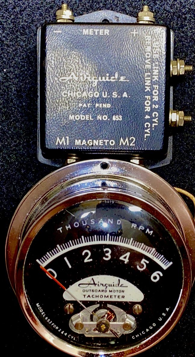
      Just picked up a vintage Airguide 653 Tach with the magneto sending unit. I plan on using it on a 64 28HP Evinrude. I looked all over the web, and found nothing on this model 653. Plenty of info for 653A but that model has the separate sender with wires coming out of it.
      Here is what I have come up with so far:
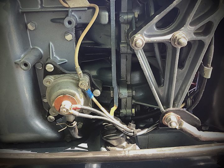
      The two top poles on the sender go to the + and – on the back of the instrument.
      On the bottom of sender are two terminals, M1 is ground, M2 is the signal from points.
      The hookup that’s throwing me off on are the right side terminals that state “Use link for two cylinder, remove link for four cylinder”.
      Does anyone have any idea what they are referring to?
      Thanks,
      Bob D

      1A56CA2B-13EB-40D1-B0C8-0C5AF770E1FE


      #264003
      dave-bernard
      Participant

        US Member

        link would be a jumper wire between the 2 posts for 4cyl. leave it of for your 28.

        #264004
        bob-d
        Participant

          US Member

          Thanks Dave, now I know link= jumper.
          The tach was hard to find,and I didn’t want to short anything out.

          Bob D

          #264364
          bob-d
          Participant

            US Member

            Looking to get the signal from the points to run to the amplifier which would generate the tach signal.
            Was planning on using the center lug from the cut off switch for the positive signal.  My only concern is that the stop switch is also connected to that lug. Will anything negative happen to the tach amplifier when I push the stop switch to ground the points to stop?
            Thanks,

            Bob D

            E1B2DD1C-5DDD-470D-B4F3-E2BB15B972D9

          Viewing 4 posts - 1 through 4 (of 4 total)
          • You must be logged in to reply to this topic.