Home › Forum › Ask A Member › Evinrude Fisherman Model 6202 Magneto question
- This topic has 13 replies, 8 voices, and was last updated 7 years, 8 months ago by
 Mumbles.
-
AuthorPosts
-
June 20, 2015 at 10:10 pm #1806
Evinrude Model 6202D 1972 Fisherman seems to have a magneto problem. The stator plate can be "jiggled" up and down, and sideways manually. This seems to be causing the gap on the points to be very unpredictable, causing hard starting, idle problems, and stopping. The schematic below may help clarify the problem. This is copied from the BRP online manual/parts list for this engine.
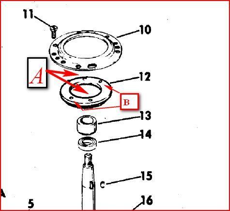
The support plate (10) plate, made of brass, is firmly bolted to the top of the crankcase with 4 machine screws (11). The retaining plate (12) is under the the support plate(10), and is connected to the magneto stator plate by 4 machine screws which go thru the stator plate into support plate 10. Two machine screws – Labelled "A" go thru the coil laminates, thru the stator plate, and into the retainer (12) at positions A. Two additional machine screws go thru the stator plate, into the threaded holes indicated by positions "B" in the retainer plate (12)
When assembled the stator plate, and retaining plate are firmly assembled together with the stator above, and the retainer plate below the the support plate (10). The 4 connecting machine screws go thru the central opening of the support plate, into the retainer pate. The outside diameter of the retainer plate is larger than the inside diameter of the support plate central opening.
Problem is there appears nothing that keeps the stator-retainer sub-assembly concentric with the the vertical axis of the crankshaft – hence it can slightly move left/right relative to the cam on crankshaft (resulting in erratic changes in point gap). Also there is a small vertical clearance between (i.) the thickness of the support plate, and the (fixed) space between the bottom of the stator and the upper surface of the retainer – hence the stator-retainer assembly can wiggle up and down a small distance around the support plate.
The retainer plate is about 1/4" thick. It has a flat surface on top, and a beveled surface on the bottom. As I found it found it assembled, the flat surface was up. Perhaps I am missing some kind of washer to go above retainer and below support plate surface to deal with the up/down wiggle???
Any suggestions how to resolve sideways movement are welcome.
Thanks in advance.
RonMJune 20, 2015 at 10:51 pm #18525The older Lightwin 3 hp used a wave washer between the parts. Maybe you have wear in the plates.
June 21, 2015 at 10:55 pm #18625The wave washer setup may make it too stiff for the twist grip throttle system. What you need is a 580871 armature plate kit, designed exactly for that situation (wear). It is for larger motors, but to the best of my rememberance will work on your 6hp also. Somebody may want to verify that. The one thing you might want to check first is see if your armature plate has a groove around the outer edge. No sure when that change came about.
June 21, 2015 at 11:46 pm #18630When my 18 hp magneto plate was worn out, I took Frank’s advice and bought that kit. It made the magneto like new- no slop up and down, and none sideways. The motor went from barely running to purring after the kit installation.
I was scared it would still be sloppy due to wear on the crankcase nose, but it turned out all the wear was on the old armature plate bushing.
June 22, 2015 at 12:05 am #18634The new bushing in the kit extends down onto the un-worn portion of the crankcase nose, eliminating lateral play.
June 22, 2015 at 4:50 pm #18676Thanks very much for the information. Will pursue this approach.
Very helpful responses.
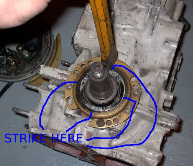
RonMJune 22, 2015 at 7:29 pm #18684A band aid kind of fix is to raise the metal on the crankcase bearing by lightly punching around it with a centre punch. I’ve done this fix on quite a few motors and it works quite well. Also, the price is right. 😀
August 22, 2016 at 9:57 pm #42519I know this is an older thread but I am trying to picture what is meant by the crankcase bearing.
Can someone please explain, or better yet show a pic of this fix?
August 23, 2016 at 12:31 am #42530The brass part 10 in the diagram above. Take a hammer and chisel/flat screwdriver, and make 4 indents around it. Will tighten up any play.
August 23, 2016 at 12:35 am #42531Like this
-
AuthorPosts
- You must be logged in to reply to this topic.