Home › Forum › Ask A Member › Restoration of 1964 Johnson JH 19A
- This topic has 9 replies, 5 voices, and was last updated 5 years ago by
 Buccaneer.
-
AuthorPosts
-
June 18, 2021 at 5:51 am #240506
Hi All
I am slowly restoring the above and I am wondering if it is safe to remove the crankcase screws, one at a time, clean them up by removing rust, painting them and reinstalling them., without disturbing the sealing between the crankcase halves………the power head paintwork is pretty good otherwise
The motor has had a hard life, but I feel that it could be a runner. My biggest hurdle is that some “mut” forgot to put the O ring back on the top of the drive shaft, resulting in the crankshaft spline being ruined……..believe it or not, the drive shaft spline is fine!.To get over the spline problem, I hope to sand blast the inside of the crankshaft spline,(making sure the area is completely sealed while blasting), then machine a square drive on the top of the drive shaft, weld up a square tube in stainless steel and imbed the square tube accurately into the crankshaft, using JB WELD. I appreciate that the lining up will have to be done very carefully!
You may be interested to know that when the motor was given to me, the drive shaft was jammed into the crankshaft with a strip of sheet steel!
Thanks in advance once again, for your much appreciate comments and suggestions.
Monte NZ
June 18, 2021 at 5:56 am #240507Hi All
Sorry, II forgot to mention that the motor is a 3hp modelMonte NZ
June 18, 2021 at 8:15 am #240511I wouldn’t remove the crankcase screws, even one at a time. I know breaking the seal between the crankcase faces isn’t likely, but it is possible.. Just not worth the risk, especially for cosmetic reasons.
June 19, 2021 at 5:42 am #240575This is just my own feeling; but I don’t think JB weld is going to stand up to the heat, vibration and torque of a drive shaft/crankshaft connection, even on a little 3 hp.To me, it seems like a LOT of work for a possibly disappointing outcome. Just sayin’. I am sure it will work for awhile, but……If it were me, I’d be looking for another parts motor with a good crankshaft and do it the way God and OMC intended. It’s maybe a lot of work; but at least when you’re done, you can be sure it will last.
Long live American manufacturing!
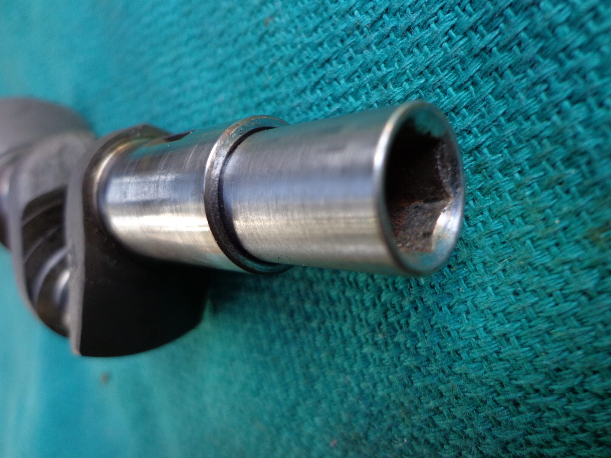
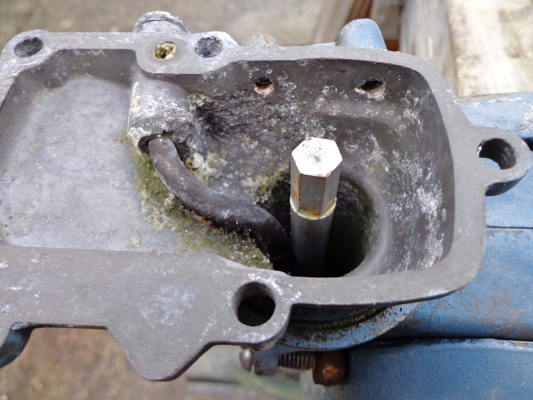
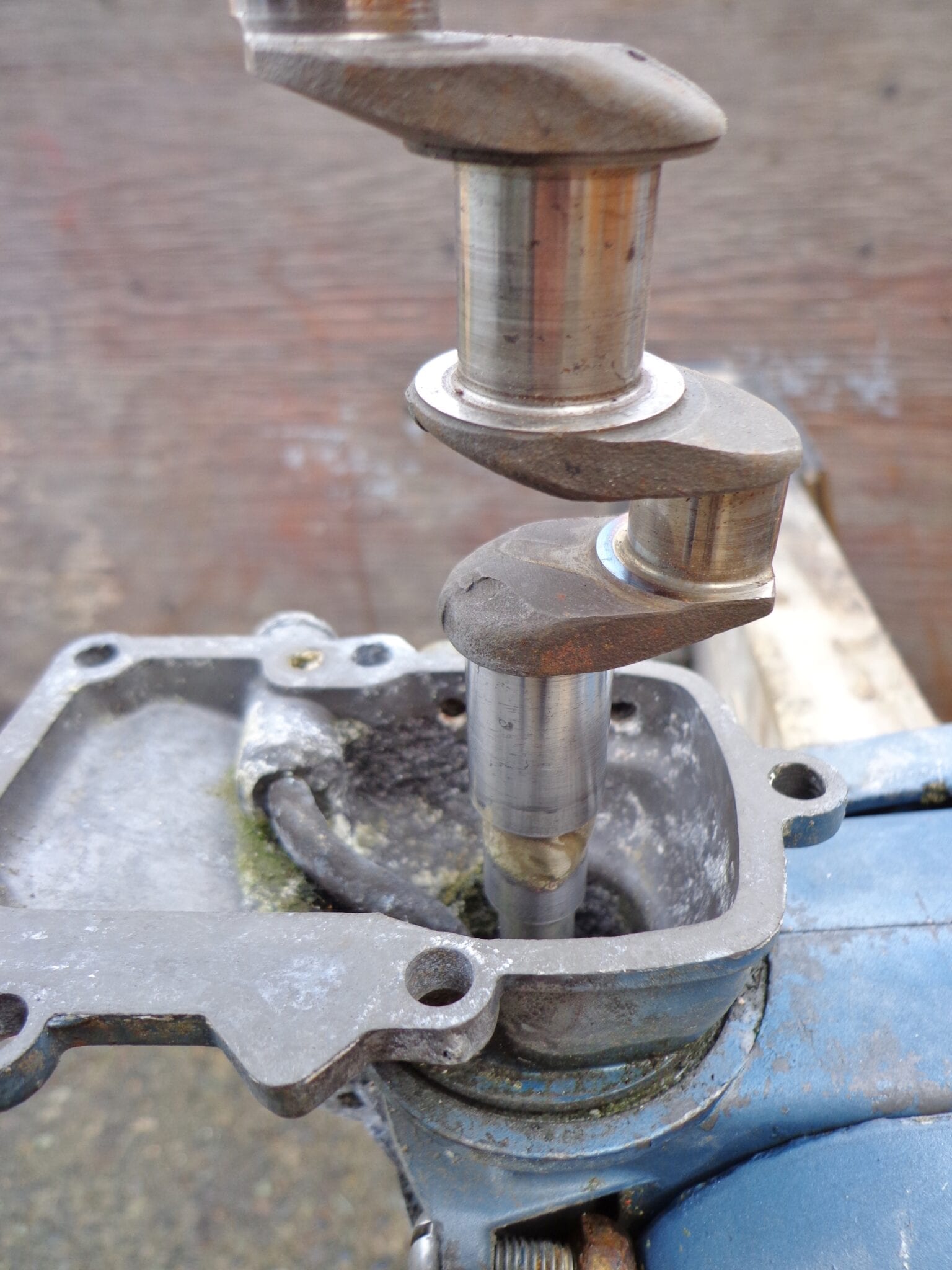
June 19, 2021 at 2:39 pm #240650There are a couple workarounds to mate the splined areas together again. One is by welding a socket onto the bottom of the crankshaft and putting a matching hex on top of the driveshaft.
The other is by grinding a flat area on one side of the driveshaft splines and welding a matching key inside the crankshaft splined area. I don’t think you’d want to do this to a shaft with good splines though.
June 20, 2021 at 6:41 am #240712Thanks all for your suggestions.
In reply to fleetwin, I won’t take the screws out to clean them up. I must admit I too wasn’t very happy about doing that.In reply to billw, I think your reasons for not using JB Weld make sense……..it may possibly work for a short time, but risky! Obtaining another crankshaft from a parts motor makes sense, but the problem here in NZ, is that there aren’t many motors here compared with USA, reason being, that back in those days we could only buy them if you had overseas currency, such as US dollars or sterling in the UK………fortunately that ruling has been done away back in 1971 ………thank goodness!!
Your suggestion Mumbles I think is the best way to go. Thanks for the photos ………certainly show your suggestion well! After looking at your photos I think I will have to dismantle the motor and remove the shaft as trying to weld in that close to the bearing would be asking for trouble……….in taking it apart it will allow me to clean up those crankcase screws that I spoke of earlier!
Am I correct in that it looks like the socket has been brazed to the crankshaft?
A chap that I know has a second hand tool shop and I am sure he will have a suitable socket. I see that the hexagonal part on the drive shaft is quite long, so I guess I will need to find a deep socket, which I could machine to being a press fit into the crankshaft, where the O ring sits. That would centralize it for welding. A friend of mine specializes in Mig and Tig welding and I am sure he would help me out.Thanks very much once again for all your help…….much appreciated!
Monte NZ
June 20, 2021 at 3:27 pm #240746Hi Monte. It must be the dead of winter and shortest day of the year in Kiwi country, eh? Just the opposite up here!
Anyway, it was a few years ago I did this experiment and I believe it was a regular 1/4″ drive socket I used and no bigger than the diameter of the driveshaft. The crankshaft was too hard to bore so I turned the socket to fit and then silver brazed the joint as I wasn’t set up for TIG welding at the time and silver brazing is much stronger than regular brazing. The short matching hex was machined using the lathe with a keyway cutter mounted in the chuck and the shaft shimmed to the correct height and held in the tool post. I might have used a boring bar holder to grab it and a small degree wheel to get the equal 60° cuts needed to match the socket. Can’t remember for sure but I do wish I had a machinist vice attachment to get the x, y, and z axis movements needed for this kind of work.
The O ring. Good point. Like I said, this was just an experiment and the parts haven’t been used in a running motor, yet. I might have to dig the parts out and go back to the drawing board. Another project on the ‘to do’ list! But then again, is the O ring still needed as there is no splined joint to protect? Doing the fix this way means cutting the good splines off your driveshaft so maybe the second way with a wedge or key would be better as the driveshaft might still be useable in another motor with good crankshaft splines and the O ring might still be functional. I can’t find the photos but have seen it done in a four horse I own and it seems to work OK and I will post the photos if I ever locate them.
The four horse has a small flat ground in the spline area of the driveshaft and a corresponding piece cut out of a bolt or something to fit this flat area of the shaft. This piece is spot welded in the crankshaft and acts as a key or wedge to drive the shaft and also keeps it tight to what’s left of the splines on the other side. Simple, but it works.
June 22, 2021 at 6:30 am #240892Hi Mumbles. You are absolutely right about it being winter down here, but our winter isn’t a patch on the ones you have in Canada! July and Aug will be cold and miserable, but here in Auckland we don’t get snow, but we will some frosts……,.pretty lucky really!
I like both your suggestions, but the second one is the method that really appeals…….welding the key/wedge into the splined area of the crank. That method would still allow for an O ring to be used again.
Another good point that you mentioned, is that the drive shaft would be forced into what is left of the spline in the crank. The fact that the drive shaft may not be able to be used on another motor isn’t a problem. I would be very interested to see your photos if and when they are found.I’m also wondering if the welding could be done without dismantling the motor.
I will have a chat with my welder friend and see what his thoughts are. Do you think it worth white grinding inside the spline area with my Dremel to get a better fit for the key/wedge?
I will keep you informed of progress.
Thanks very much once again!
Monte NZ
June 23, 2021 at 6:18 am #241002Hi Mumbles
Attached is a shot of the inside of the crankshaft showing the rusted spline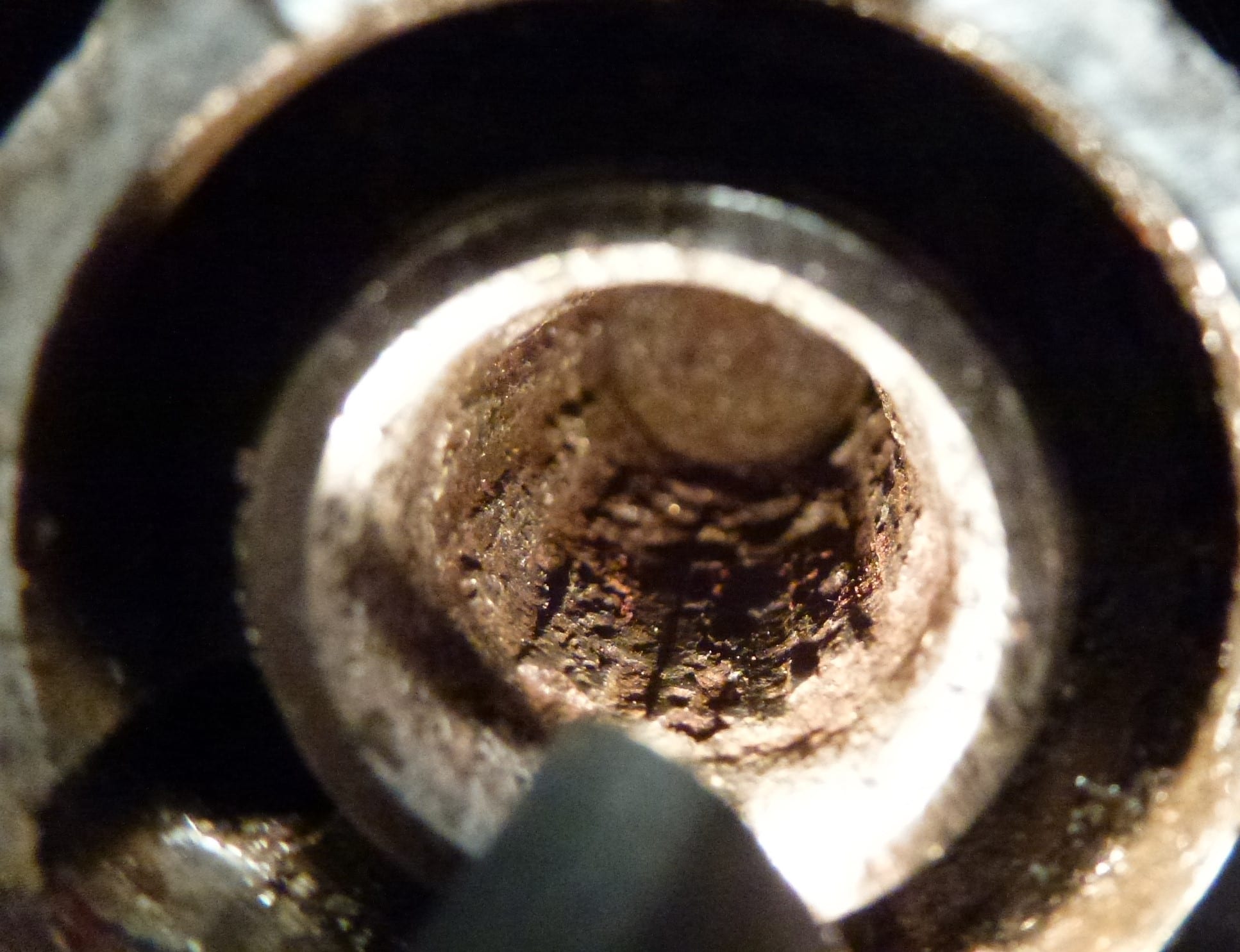
Monte NZ
PS This is the first time I have tried to attach a photo……..hope I have done it correctly!June 23, 2021 at 8:36 am #241006Dang, doesn’t look like any splines left!
Too bad they don’t make a “spline insert” where the end of the crank
could be bored out and the spline inserted and fastened some how.Prepare to be boarded!
-
AuthorPosts
- You must be logged in to reply to this topic.