Home › Forum › Ask A Member › 1940 Johnson HD-15 Magneto testing
- This topic has 37 replies, 3 voices, and was last updated 6 years, 10 months ago by
 Buccaneer.
-
AuthorPosts
-
June 25, 2017 at 1:23 pm #60291
If it doesn’t have 2 lobes then you would mark flywheel 180 degrees from the other mark. Piston would be toward top of cylinder for that respective mark. You may not need to run engine you might use an electric drill or something to spin flywheel while checking.
Joe
June 25, 2017 at 1:52 pm #60294Something I just thought of.
Using stevens meter you could snake a wire to the primary positive side of coil which is the one you have the red alligator clip to in first pic. Then place flywheel on motor where points have just broke for that cylinder and with stevens on spark check see if you get spark on both cylinders. Then rotate flywheel 180 degrees till points just break and see if you get spark on both plugs. That might also help detect if brushes are working correctly or if the ground brass plate in flywheel is indeed grounded correctly you should only get one spark on one plug wire.
Just thinking what I might try.
Joe
June 25, 2017 at 3:00 pm #60297Joe, I was just out in the garage, and thinking about "hi-potting" the
flywheel. I wonder if doing so would de-magnetize or damage
the flywheel magnets? I forgot to put the keeper on last night
as it was 🙁 . I do have a magnet charger though, so maybe
not a big deal?BTW, The cam does have "two" lobes.
Regarding your last idea, the flaw might be that in order to
get the coil to fire on the Stevens tester, or otherwise,
one side of the secondary must be grounded, therefore
I don’t see how you’d tell if both plugs fired at any given time.
Am I thinking wrong here?
Thanks, BuccUPDATE – Retested the coil itself on the Stevens using the
correct polarity this time, and the coil does fire nicely
at a lower amperage, between 1.5 to 1.7 amps, well
within specs.I tried Joe’s idea (brilliant, btw) of hi-potting the
flywheel and checking for carbon tracking in the
bakelite plate, by hooking up the Stevens to an OMC coil,
and putting the flywheel in the
secondary circuit. I found no carbon tracking, but it
drew a nice arc while probing if you got too close to
the flywheel or brass contact in the bakelite plate.
Amazed myself by not getting shocked 🙂
The flywheel magnets did not appear to be affected.Just had a thought now about the .20 uf cap I installed.
It has not been testing using the Stevens, for leakage, etc.
I was thinking about a Kawasaki motorcycle my Uncle was
working on back in 1975. It was running very irratic, much
like my HD-15. Said Uncle replaced the condenser and it
ran great.
Could my problem be as simple as a condenser?
Keep the thoughts coming, I’m almost having fun playing
mad scientist! Unfortunately, I have to knock off
for the day and go to a picnic.
Thanks.Prepare to be boarded!
June 25, 2017 at 11:31 pm #60341I’m sorry had to step out today also.
You wrote:
"Regarding your last idea, the flaw might be that in order to
get the coil to fire on the Stevens tester, or otherwise,
one side of the secondary must be grounded, therefore
I don’t see how you’d tell if both plugs fired at any given time.
Am I thinking wrong here?"When the flywheel spins in real time it grounds one side of secondary automatically if brushes and flywheel tab and no cracks in bakelite and its all working.
That is why I was thinking you could put your flywheel in the position on engine and where coil would normally fire that should kill one cylinder fire if brushes and tab are working. Snake a wire and check with stevens meter.
By doing so your checking both plug wires with stevens meter to see if the other side of coil secondary is grounding out as it should with bakelite brass piece in flywheel . The brass tab did show a correct ground when you bench checked flywheel with omc coil and made sure tab was grounded and no cracks in bakelite. You did get spark with the probe when you got near brass tab but no spark checking bakelite thats a good thing. it means Good Ground on tab and good bakelite no cracks?? Hope that makes since.
One side of secondary should automatically be grounded when coil fires by flywheel brass tab and brushes are is working correctly which I suspect it isn’t. You have 2 lobes on cam so when one cylinder fires one shouldn’t because brushes. When cylinder fires one shouldn’t because other brush and by shouldn’t I mean they can’t or motor will never run right.
One more test to possibly try. Use stevens meter to fire your coil and see if both spark plug wires put out spark with flywheel off.
By checking one plug wire for spark then the other with flywheel off. I bet you a bunch of money that they both fire when one is not grounded and that will help explain the need for the brushes and how important they are for correct ignition results. What kills one side in real time is the brushes grounding one side or doesn’t kill the other side then you get double firing which I think you may have.A zephyr has 4 cylinders 2 coils which means 1 coil has to fire 2 plugs/cylinders at same time but one is one piston is in the tdc position and one in the bottom dead center. Since their is 2 coils on a zephyr 4 cylinders more than likely 2 lobes they alternate all that and don’t need the bakelite contraptaction you have in your flywheel.
Check your capacitor for leakage also. Try a good tested condenser with good leakage reuslts. The motor does also sound like a capacitor that may be breaking down. With one side of coil grounded everytime it fires I would guess a good condenser/capacitor is even more critical. It really sounds to me like an ignition issue.
If you can’t get it worked out we might try one of my home made red atoms in it since you have a type of distributor using the flywheel and brass tab. I have only had success with the omc engines 2 cylinders 1950-1960ish but both magnets are on one-side of flywheel your magnets are on both sides of flywheel but with the flywheel used for distributor who knows might work. I have heard folks have used them in Zephyrs and they also have multiple magnets.
I hope that helps,
Joe
June 26, 2017 at 2:24 am #60358Joe wrote –
When the flywheel spins in real time it grounds one side of secondary automatically if brushes and flywheel tab and no cracks in bakelite and its all working.That is why I was thinking you could put your flywheel in the position on engine and where coil would normally fire that should kill one cylinder fire if brushes and tab are working. Snake a wire and check with stevens meter.
By doing so your checking both plug wires with stevens meter to see if the other side of coil secondary is grounding out as it should with bakelite brass piece in flywheel . The brass tab did show a correct ground when you bench checked flywheel with omc coil and made sure tab was grounded and no cracks in bakelite. You did get spark with the probe when you got near brass tab but no spark checking bakelite thats a good thing. it means Good Ground on tab and good bakelite no cracks?? Hope that makes since.
I think I understand the above, in that I should simulate "real life" operations of the magneto
grounding system with the flywheel on. I believe there’s a hole in mag plate to snake
a wire through, and if the Stevens doesn’t "light up" when it should, then the grounding system
isn’t working correctly.With the mag plate on the bench, I did test the continuity of the carbon brushes and their springs today, by hooking a
wire with an aligator clip on each end. One end to the brush and the other end grounded to the
mag plate. (instead of grounding one plug wire to the mag plate) I then fired the coil with the Stevens.
I did this with the other carbon brush as well, not finding any problems, such as a poor
soldering job, etc. While testing this way, I rubbed the spark plug wire end (that had it’s
brush grounded) on the mag plate, and got no arcing, which is good!One more test to possibly try. Use stevens meter to fire your coil and see if both spark plug wires put out spark with flywheel off.
By checking one plug wire for spark then the other with flywheel off. I bet you a bunch of money that they both fire when one is not grounded and that will help explain the need for the brushes and how important they are for correct ignition results. What kills one side in real time is the brushes grounding one side or doesn’t kill the other side then you get double firing which I think you may have.I do not believe the Stevens unit will fire the coil "unless" one side of the secondary is grounded, but
when the HD-15 is actually running via the flywheel magnets, and spinning many rpms, I’m
guessing there’s more likely to be out of sequence firing of the coil, is something is amiss??A zephyr has 4 cylinders 2 coils which means 1 coil has to fire 2 plugs/cylinders at same time but one is one piston is in the tdc position and one in the bottom dead center. Since their is 2 coils on a zephyr 4 cylinders more than likely 2 lobes they alternate all that and don’t need the bakelite contraptaction you have in your flywheel.
I’ve wondered about systems that fire the plug, as you say at BDC, and
how they don’t "upset" they system by lighting off residual fumes.
Don’t even four cycle lawn mower engines fire at BDC?Check your capacitor for leakage also. Try a good tested condenser with good leakage reuslts. The motor does also sound like a capacitor that may be breaking down. With one side of coil grounded everytime it fires I would guess a good condenser/capacitor is even more critical. It really sounds to me like an ignition issue.
Will pull the cap tomorrow and test it for kicks,
and it will (or a new one) have shrink tube on
the leads when installed.If you [/b]can’t get it worked out we might try one of my home made red atoms in it since you have a type of distributor using the flywheel and brass tab. I have only had success with the omc engines 2 cylinders 1950-1960ish but both magnets are on one-side of flywheel your magnets are on both sides of flywheel but with the flywheel used for distributor who knows might work. I have heard folks have used them in Zephyrs and they also have multiple magnets.
I hope that helps,
Joe[/quote]
Thanks for all the help Joe. Will report back tomorrow some time!
BuccPrepare to be boarded!
June 26, 2017 at 11:17 am #60374"A zephyr has 4 cylinders 2 coils which means 1 coil has to fire 2 plugs/cylinders at same time but one is one piston is in the tdc position and one in the bottom dead center. Since their is 2 coils on a zephyr 4 cylinders more than likely 2 lobes they alternate all that and don’t need the bakelite contraptaction you have in your flywheel"
I believe I made a mistake here in this statement. It should have been when 1 coil fires it fires 2 cylinders at the same time. Since their are 4 pistons 2 are at TDC at the same time and 2 are at BDC so it fires the 2 at TDC. Sorry for getting that part wrong but 1 coil is firing 2 cylinders at TDC at the same time.
On my 40hp Yamaha (CDI Ignition) outboard I rebuilt last year 1 coil fires both cylinders also. It is called wasted spark so both plugs fire the same time everytime. 1 piston is at TDC and one is at BDC. I sheered a flywheel key last year and the flywheel had slipped to right at 180 degrees from where it should be but it would still run just not correct. Took me forever to figure out it was a flywheel key.
I think your motor has no reed valves? and an unusual way of getting fuel (rotary valve) I think thats why it has the brushes are used to kill spark to the cylinder that doesn’t need it because piston is at BDC and fuel fumes are present. I think the zephyr also uses a rotary valve I have 3 of them and love them.
Did you ever determine what size condenser/capacitor value to use? Most the 1940 OMC smaller engines like the zephyr on the chart are showing .09 to .125 I wonder if by having less capacitance would that possibly help the situation?? Your using .2 just wondering by going down to .09 which would be half if that might somehow weaken the spark and allow the brushes to work better? You may still want to see if both plug wires fire with the Stevens Meter hooked up to coil and 1 not grounded with the .2 I suspect they will.
hope that helps,
JoeJune 26, 2017 at 12:12 pm #60377quote joesnuffy:”I think your motor has no reed valves? and an unusual way of getting fuel (rotary valve) I think thats why it has the brushes are used to kill spark to the cylinder that doesn’t need it because piston is at BDC. I think the zephyr also uses a rotary valve.
Definitely no reed valves in these units.Did you ever determine what size condenser/capacitor value to use?
The charts says to use a .18 mfd condenser, and I figured a .2uf cap
was close enough, but that could be something to experiment withYou may still want to see if both plug wires fire with the Stevens Meter hooked up to coil and 1 not grounded with the .2 I suspect they will.
I’m guessing I can get both sides of the coil to fire at once if one secondary is hooked
to the Stevens unit and the other is close enough to the mag plate / ground, or hook it up
to a spark plug with it’s base grounded?
Will read through all your thoughts and try to formulate a "battle plan" for today!
Thanks again!hope that helps,
JoePrepare to be boarded!
June 26, 2017 at 11:39 pm #60427Here’s what I did today to look for problems on the HD-15 magneto.
Tested the .2uf cap on the Stevens, and found "zero" issues with it,
but installed a new one with shrink tubing on one lead for good luck.
I would have tried a different capacitance cap, but all I found was
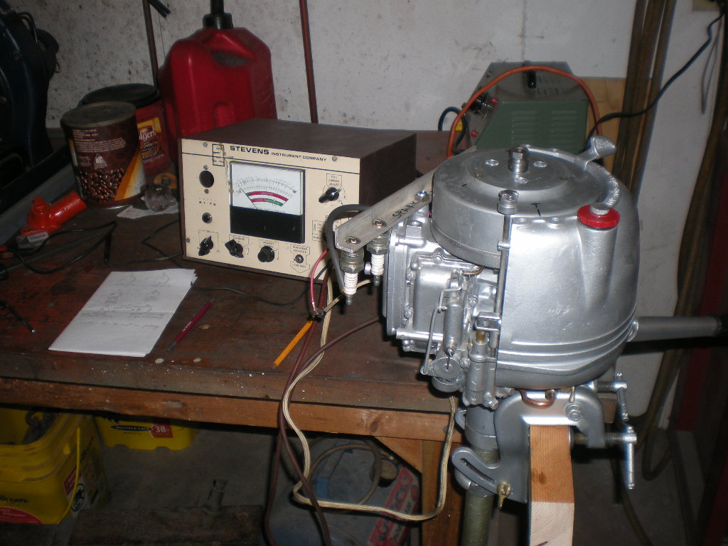
an empty bag of .15 uf caps 🙁I then tested the coil on the Stevens, with the mag plate and flywheel installed
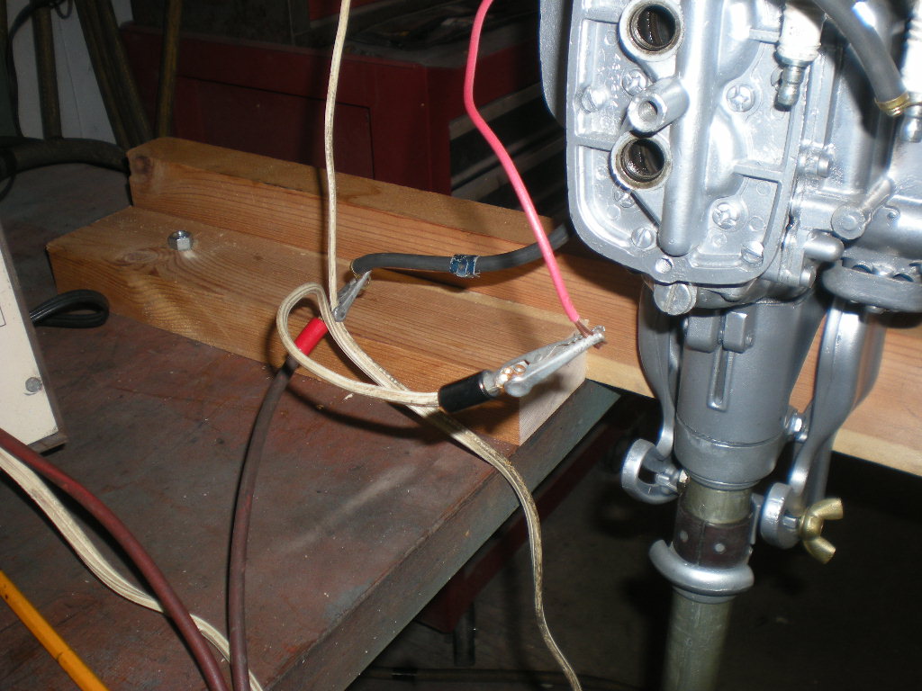
on the power head. I snaked a wire thru the bottom of the mag
plate and hooked it to the coil primary lead at the points connection.
The points were separated with a piece of paper, and the capacitor
dis-connected. One spark plug lead was hooked to the Stevens,
and the other hooked to a spark plug with it’s base grounded
to the power head.
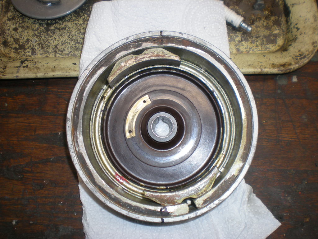
The "grounding brushes" on the coil secondary towers appeared
to be doing their job, in that when the cylinder being tested
was near TDC, I’d get spark only from that side of the coil,
hence the other side was grounded properly by the carbon brushes.
When neither brush was being grounded by the brass contact
in the flywheel bakelite plate, I’d get fire from both sides of the
secondary, that is the Stevens would like up, and the spark plug
for the other cylinder.
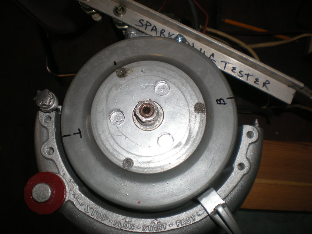
I noticed that the brass grounding contact in the flywheel
bakelite plate is "not" equidistance between the markings for
Top cylinder TDC, and Bottom cylinder TDC, therefore when
running the Stevens and turning the flywheel it would switch
over from firing only one plug wire sooner as it neared the Top cylinder TDC
than when it neared the Bottom cylinder TDC, or vice-versa.
I did remove the bakelite plate, but I’m 99.9% sure it’s correctly
relocated. 😕
I think I’ll put it all back together and see how it runs, (or if)
and if it’s the same irate running Johnson, then I’ll
try and hook up a timing light with it running and see
what that tells me!
Attachments:
Prepare to be boarded!
June 27, 2017 at 12:13 pm #60452That’s good work!!!
I don’t think the grounding tab on bakelite would have to be right on the money just close since the points have to break to fire the plugs.
The only thing I can think of that you could check since bakelite was altered if it doesn’t run right or before you put motor back together is with your wire snaked to the magneto attach it to the points so you will know when points break using a multimeter or stevens tester in continuity mode and see if tab is in the correct spot that could be done with a second multimeter using continuity check with a multimeter attaching it to ground and the ignition wire to see if it in fact does not have continuity when points break for each respective cylinder when that piston is on bottom stroke=no continuity on plug wire when points break. If their is continuity when points break that would be a double fire for engine and the bakelite and tab are off to much resulting in double fire and a engine running erratically.
(You might have to attach multimeter wire to both spark plug wires to establish continuity which will still break when tab makes contact with one of them which would work also if attaching multi meter to one plug wire and ground doesn’t give you continuity. I read somewhere you test for continuity with coils with 2 ignition wires from plug wire to plug wire.)
The way I see this engine working correctly is continuity to the 1 plug wire is broken before the points break for each respective cylinder. If you get lucky and have continuity between the 2 plug wires that will make it a little easier to test (otherwise you would have to switch the multimeter to the other plug wire to and ground to test). As you rotate the flywheel continuity between plug wires should break for each cylinder before the points break. The continuity between the secondaries should also stay broken till the points break.
Hope that helps,
Joeps I think you said you have a buzz box you could also use that to see when points break.
June 27, 2017 at 2:53 pm #60466I went and read another thread where you had posted this info:
-Coil Secondary 6.29 K ohms
Primary .8 K
-Kill Post working as designed
-Flywheel magnets – "So-so to Iffy"
-Flywheel brass grounding contact to "ground", "0 to .7" ohms resistance.
-The carbon brushes have good continuity to the coil,
and not grounded out anywhere.
-New plug wires with good readings at terminals.6.29K ohms on the secondary which that is how I would test motor. Hook up multimeter to secondaries. Use the snaked wire to go to points connection using either a buzz box or multimeter slowly turn flywheel in the direction motor runs. Secondaries continuity should break before the points break. The secondary continuity also has to stay broken until points break. If all that checks out then bakelite is in the right position.
Hope that makes sense,
Joe
ps I also read where mumbles fixed a crack in one of his brush holders with clear fingernail polish. If motor still doesn’t run right you might consider coating the entire outside of both brush holders with clear fingernail polish that might help prevent arching if its happening.
-
AuthorPosts
- You must be logged in to reply to this topic.