Home › Forum › Ask A Member › 0584477 Replacement OMC coil
- This topic has 16 replies, 8 voices, and was last updated 5 years, 4 months ago by
geary.
-
AuthorPosts
-
January 24, 2021 at 1:22 pm #228683
Much like Mr W.Mohat’s article in the last Outboarder old capacitor casing are emptied out, I drilled the bottom side edge with a small 1/16 hole to pass and solder one capacitor .wire on the side. I prefer the side soldering vs bottom soldering just to keep the capacitor sitting flat of the mag plate surface.
the top wire is bent 90 degrees twice to get it centered on the cap. top
The top wire exiting the capacitor is wrapped with a few layers of tape to keep it from touching the edge of the emptied casing.
After centering the capacitor in the casing I filled it with epoxy glue
the top wire is then soldered to the old capacitor wire so it can be reattached to the point screw
Before soldering the end wire I slipped on a one inch piece of shrink tubing to cover my solder joint.
Sliding it back over the solder joint and shrinking it makes for a nice connection
Mr.Mohat method of emptying the old casings makes for a nicer finished capacitor rim but I simply shaved off the capacitor rim on my grinder and out comes the whole contents.
btw some capacitors have a carboard insulator on the inner surface of the casing so if you have one keep it and use it !
all that said and done one could probably just connect each capacitor end wire without a casing one to ground one to the point screw ….
Joining AOMCI has priviledges 🙂
-
This reply was modified 5 years, 5 months ago by
JACQUES.
January 24, 2021 at 1:26 pm #228685Have you guys read the article yet on capacitors in this months Outboarder magazine? It’s quite interesting and you might want to read it before buying any caps which might not hold up.
Thanks for posting the photo.
I read the article, and I’ve been wondering what these ceramic caps
looked like up close, and what’s there to solder the wires to.
Mr. Mohat mentioned using the leads cut of from some type of
little resistor.
Could one get by by simply using some insulated automotive wire?Prepare to be boarded!
January 24, 2021 at 1:53 pm #228686Crosbyman, great write up. You wouldn’t happen to have a pictures of the process and or a finished capacitor?
Maybe I should start reading the articles in the Outboarder instead of heading first to the color pictures in the center!
I guess my old habits of “reading ” Playboy never die!
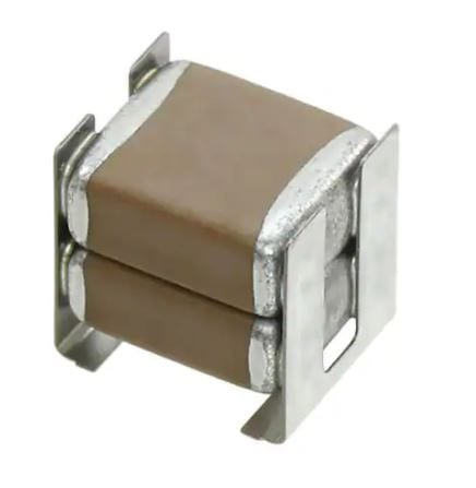
Bob DJanuary 24, 2021 at 1:57 pm #228687In the photo it looks like two caps soldered together so the leads must get soldered to the end pieces which are holding them together. In the article he mentions insulating the cap with epoxy or something before stuffing it in an old can. The lead to the points would definitely have to be insulated somehow. Maybe with a piece of that yellow spaghetti insulation I mentioned in another post.
I think these X7R caps are quite small (surface mount?) so I think I might order some to see what they are all about.
January 24, 2021 at 4:05 pm #228707PICS… NOT A BEAUTY BUT….SHOULD WORK
220.7 NANOS …. .22UF
Joining AOMCI has priviledges 🙂
January 24, 2021 at 4:37 pm #228711previous post poofed… ?
Grumbles… I agree 100% ceramics are the best option I am just trying the plastic 630v caps although Mr.Mohat article showed preferrence to 850’s
I used these 630’s .22uf in his version 1 test box and they work fine up to now.
soldering small ceramics may not be eveyone’s cupcake and they are much more pricy. IF anyone had issues with 630v caps hopefully they will chime in.
I have no info (specs) on the tolerance level of 580321 caps (anyone ?) 400-600- 800 ?? volts
Joining AOMCI has priviledges 🙂
-
This reply was modified 5 years, 5 months ago by
January 30, 2021 at 4:06 pm #229094Guys,
The caps in the picture are not the ones Bill suggested for me to order ! These that I ordered are a little different looking and are less than a 1/4″ square, each end has a metal surface that you can solder to. Actually there are two options for mounting them ! For those that want the magneto to look authentic you can mount them in the old condenser can and solder a wire to each end of the cap, then solder one end to the condenser can and run the other wire out to connect to the points connection. Because these caps are so tiny you can fill the condenser can with epoxy and they look just like the original ! The mounting depends on the motor you are replacing them in !The other option is if you’re not a purest, after you solder the wires on, coat the capacitor with a little epoxy and put a piece of shrink tube over it. I mounted these in a 10hp Scott Atwater and was able lay them under the coil laminates and wired them in with plenty of room. And they worked great !
Gary
-
This reply was modified 5 years, 4 months ago by
-
This reply was modified 5 years, 5 months ago by
-
AuthorPosts
- You must be logged in to reply to this topic.