Home › Forum › Ask A Member › 1948 Gale Hiawatha 5HP
- This topic has 53 replies, 9 voices, and was last updated 8 months ago by
Steve young.
-
AuthorPosts
-
August 24, 2020 at 10:12 pm #212549
Well guys, I’m almost ready to give up on this 1948 Gale 5hp. I got the new rubber pump from Brian Wilcox and it is still running hot. I did the drill test and it didn’t push much water. Slightly more than the old original. When I run the motor it gets hot almost instantly. I don’t see any water spitting out the slit. And the motor sides are burn your hand hot.
The motor runs cool if you put hose water pressure to the bottom hole in the lower unit stem (lower unit removed). We ran the engine a few minutes this way on idle with hose running and the motor sides were warm but not searing hot.
How do I get more water pressure out of this? Are the prop holes supposed to be lined up with the hub holes? Or offset? I have the holes lined up.
August 25, 2020 at 8:27 am #212580Water holes alignment does not matter. In fact, you can barrel cruise with no prop.
August 25, 2020 at 1:22 pm #212631Can anyone confirm how much water pumps out of the 90 degree bend in the upper portion of the lower unit when you use a drill. I removed the lower unit by removing the two screws and used the drill on the drive shaft. I had my drill set to high.
I will try to post a video or a link to a video on youtube tonight. I only get water when the drill is at full speed. It does not seem like enough pressure to get all the way up to the head.
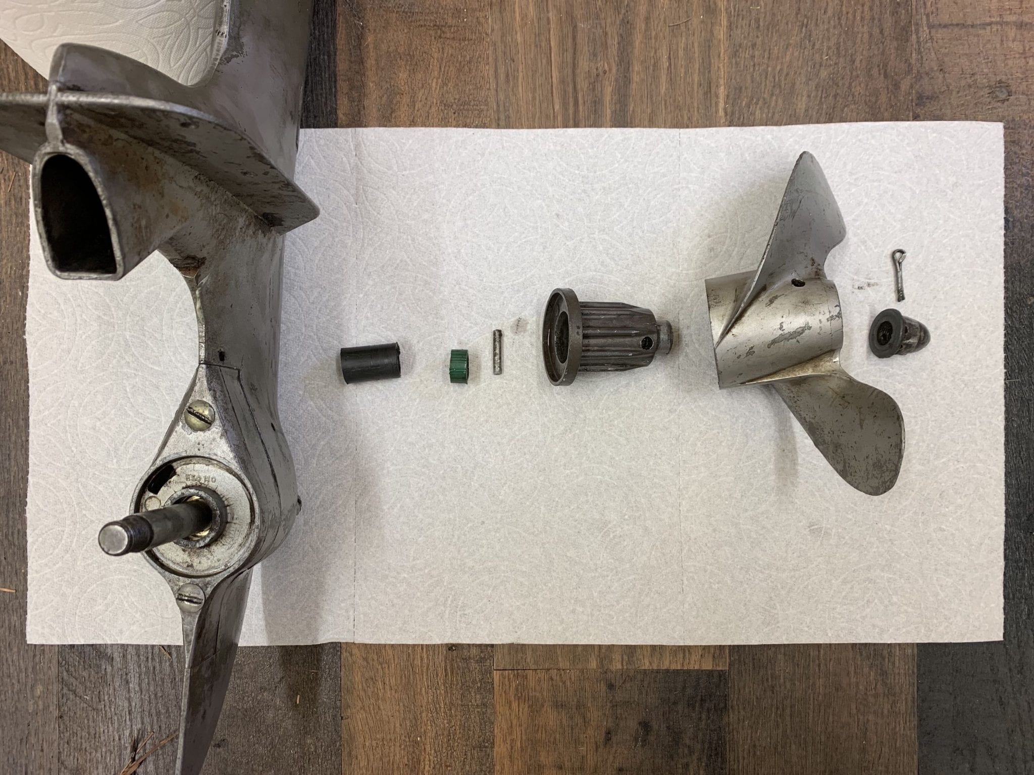
August 26, 2020 at 10:48 am #212717Wow, I have some extra parts! I can see that those extra parts are what was probably blocking the water flow.
One being the green hose looking tube and the other the Black hard plastic tube piece. Both were stacked and fit over the prop shaft. Weird that someone would do this.
Note: I did not take the rubber prop shock absorber out of the prop for this picture.
-
This reply was modified 5 years, 10 months ago by
 Mumbles.
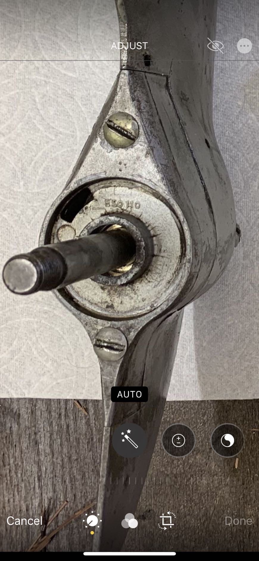
I see a bunch of daylight around the shaft where it comes thru the cover. Without pulling a motor apart, I don’t recall there being a seal here but I’ll bet you that’s what the previous owner used the bit of rubber hose for.
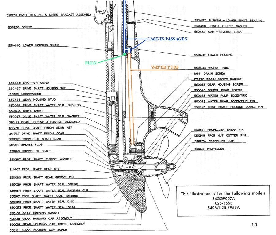
August 26, 2020 at 11:32 am #212725Looking at the parts diagram I don’t see a seal there unless it was built into the Gear Housing Cap Cover #22
I will check again but I believe I have all the parts and in the correct order for the water seal on the back side. It doesn’t look like I’m getting much leaking into the gear case.
I’ll investigate tonight. I just don’t have the volume and pressure it needs. I was going to try to run it without the prop tonight just to see if it improves in some way. I have disassembled the prop and checked the holes and passage are clear from the prop to the hub.
Like I said, I think it’s a problem somewhere from the pump to The 90 transition and attachment to the upper portion of the motor. When I put the hose to the next section (the small hole in the tube going up the head) the head stays cool.
I wish, I could examine one of these motors in action. It seems almost impossible that this small eccentric pump could pump water all the way up through that head. I know it does but it’s hard to imagine.
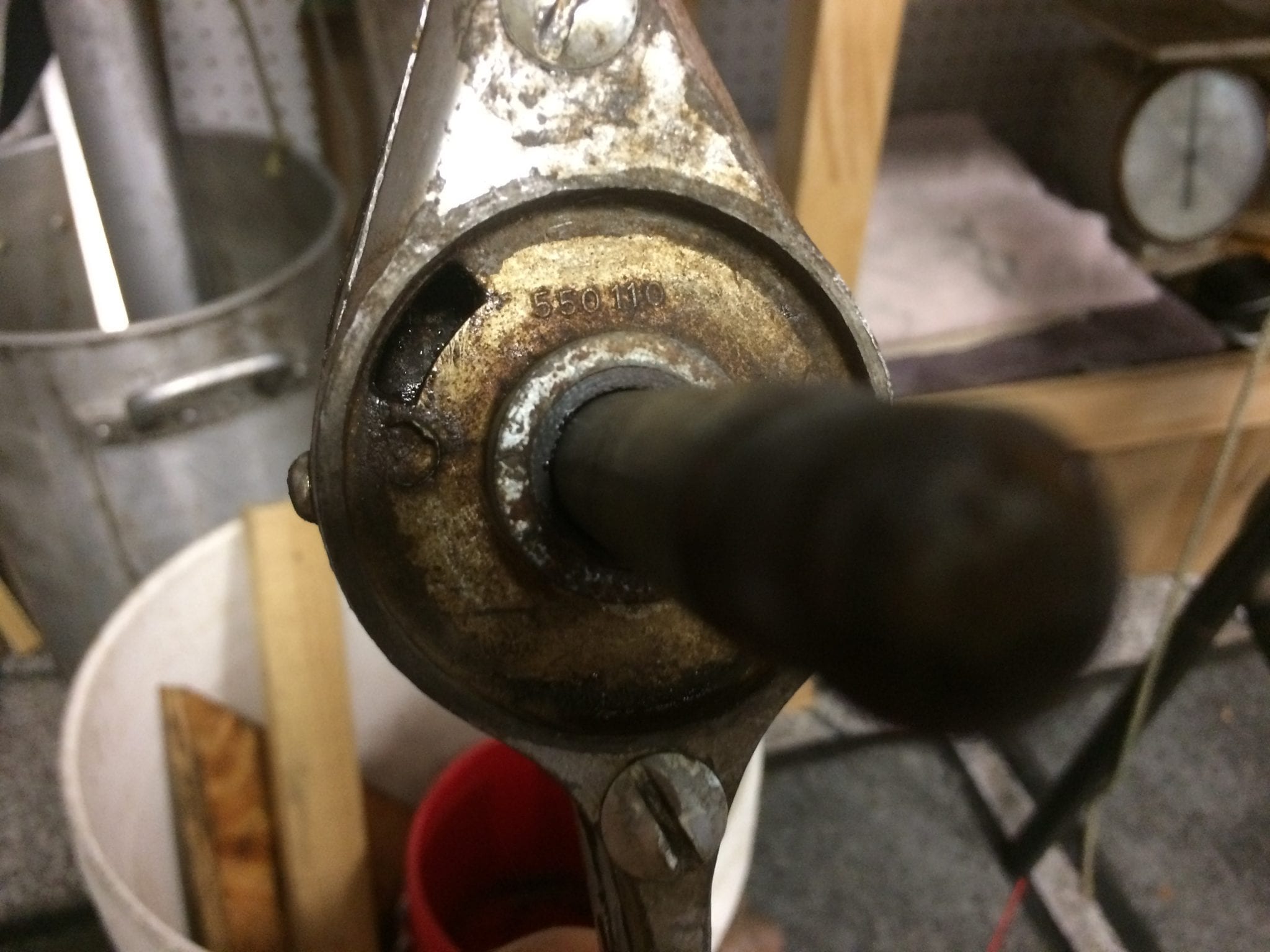
August 26, 2020 at 3:00 pm #212741My 1948 Goodyear has a bronze bushing in plate #22 which yours looks like it’s missing. Parts sheet posted does not show a bushing in that pale?? bushing could act as a seal and some water escaping there when running.
August 26, 2020 at 3:10 pm #212743Rest assured, those pumps do provide plenty of water if working correctly. I think somebody was trying to re-engineer it with those extra parts.
Let’s start over at the beginning. The important items to consider are the fit of the rubber rotor. It should fit the brass eccentric closely, and just touch the inside of the pump housing at some point as it goes through it’s wobble action. Also, it should contact the inside of the cap cover, in other words no space between the rotor and cap cover. Lastly, no big wear or big pits..
How it works: At some point in the rotor’s wobble cycle, a gap between the rotor and housing fills with water through the rectangular slot in the cover. As the rotor continues through the cycle, the gap moves around to the other side, taking it’s gulp of water with it. Finally, the gap disappears, squeezing the water up through the pump outlet and water tube. As long as the rotor is touching the housing on the outside and proper height, the water will not escape from the gap as it moves from one side to the other. That is it is a positive displacement pump. One last thing, the tab on the rotor does not pump anything,, it only separates the inlet side of the pump from the outlet side.
The propeller— As the motor is running and moving forward through the water, notice the pump inlet as facing aft–away from the water flow direction. So, the holes in the prop are on the pressure side of the prop blades, which feeds water toward the pump inlet. Low tech, but so simple that it works.
Now for that 90 degree turn. I haven’t had that many apart to be intimate with that part. But I think I have some pictures. Will look.
August 26, 2020 at 3:17 pm #212745Ah, I found it. I wonder if the green “plug” is in place in your motor?
 August 26, 2020 at 11:10 pm #212797
This is all great information. I ran out of time tonight to investigate but will dedicate some time tomorrow evening.
I will get some answers for everyone on what I find. I will check for this plug near the 90 degree cooling line.
Can anyone confirm if hub cover #22 on the parts diagram is supposed to have a bushing or seal. I know it’s not listed in the parts diagram but it may have been built into this part. Or is there supposed to be all this space around the prop shaft.
-
This reply was modified 5 years, 10 months ago by Mumbles.
August 27, 2020 at 8:42 am #212804Here’s a photo of my #22 plate with bushing. Bushing must be part of the plate.It looks as if some one drilled or reamed your bushing out and tried substituting the short rubber piece of tubing for the bushing to help seal pump. The long piece of tubing was probably meant to keep short piece in place.
-
This reply was modified 5 years, 10 months ago by
-
AuthorPosts
- You must be logged in to reply to this topic.