Home › Forum › Ask A Member › 1962 Gale 40 hp Wiring
- This topic has 11 replies, 3 voices, and was last updated 6 years, 7 months ago by
 Buccaneer.
-
AuthorPosts
-
October 28, 2019 at 7:45 pm #186045
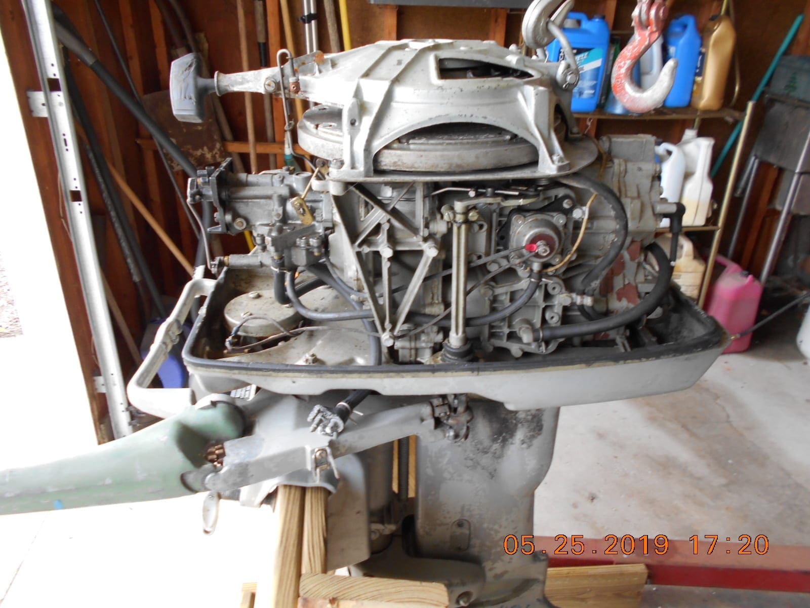
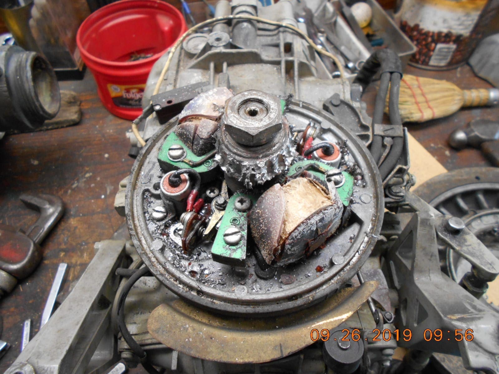
The 40 hp Gale is going back together after “way too long”.
I believe I have the carb synchronized to the mag okay,
safety switch set, and fuel saver rod set okay per manual.Just want to make sure I wire up the kill button (manual start motor)
to the mag and overspeed vacuum switch correctly.
From what I can see on my old photos before tearing the motor down,
along with a little logic, and hopefully “luck”, I think these items
should be wired as in my drawing.
Can anyone confirm?
Thanks!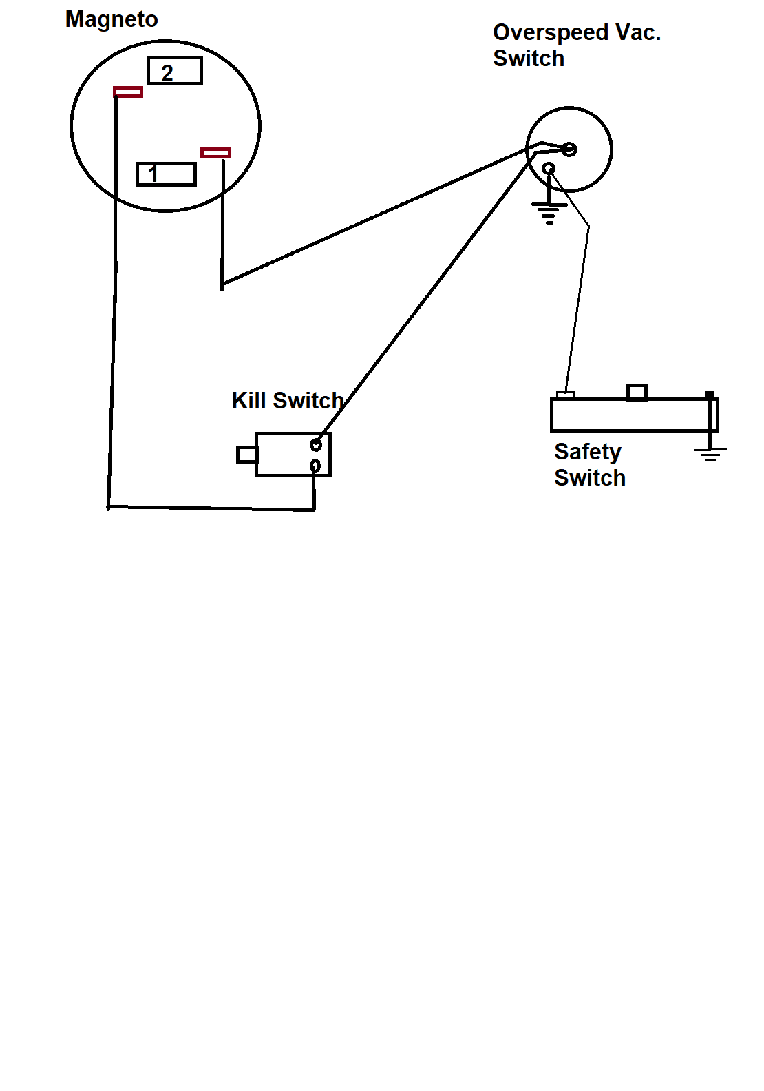
Prepare to be boarded!
October 28, 2019 at 9:33 pm #186052It is wired right, but should not show a ground at the vacuum switch..The vacuum switch is grounded through the safety switch. You did good –


-
This reply was modified 6 years, 7 months ago by
garry-in-michigan.
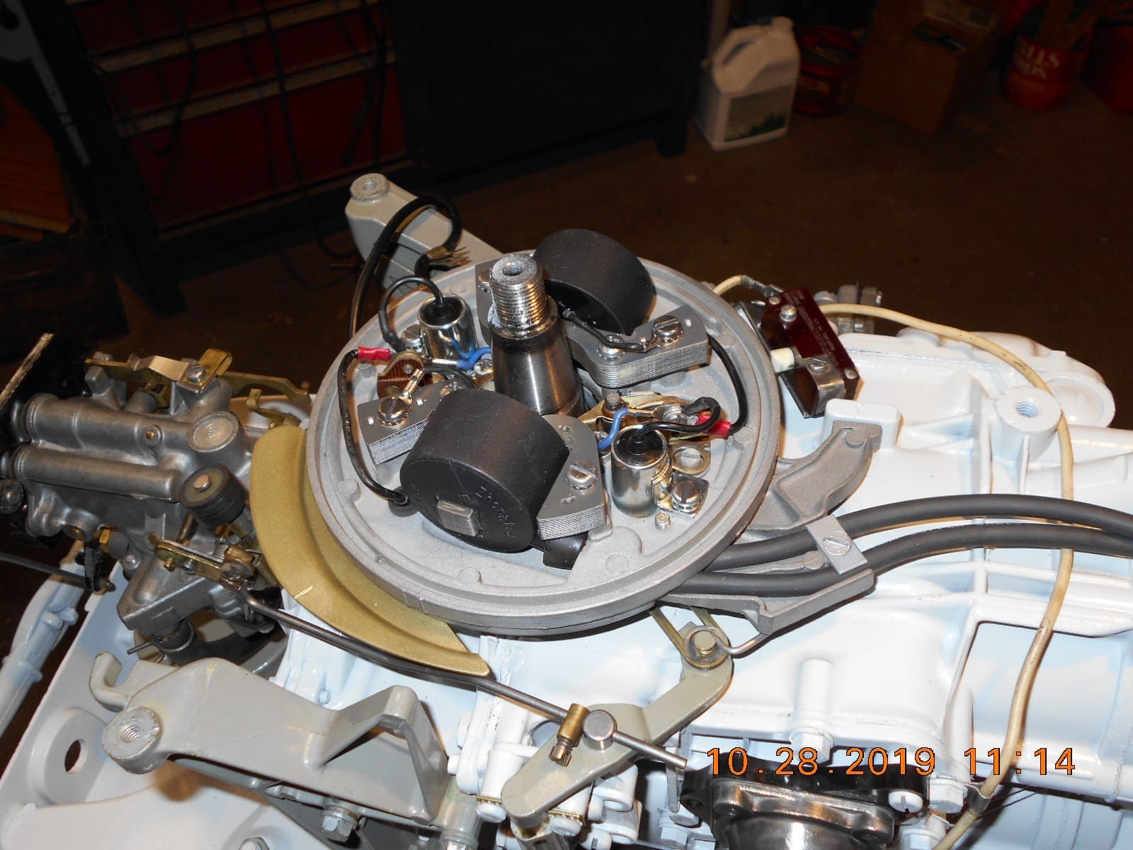
October 28, 2019 at 9:41 pm #186054Diagram is correct, but I see a couple of other problems. Kill wires will probably rub on flywheel. They normally come up through the grommet, then go under the coil to the points on right side of coil.
Looks like the fuel saver rod isn’t quite right. With throttle against stop as shown, the set collar should be just touching, and roller should still be on the cam. Looks like yours is already holding roller away from the cam a bit.
Well diagram is “almost” correct——-I think. If I remember correctly, #2 goes to center of vacuum switch, not #1. Probably doesn’t really make any difference (?).
October 28, 2019 at 9:44 pm #186055It is wired right, but should not show a ground at the vacuum switch..The vacuum switch is grounded through the safety switch. You did good –


Yeah, I missed that. It should not show the ground symbol at the vacuum switch.
October 28, 2019 at 9:54 pm #186056Fuel saver rod connection to the carb looks funky. Can’t figure out why from the camera angle.
October 28, 2019 at 11:31 pm #186062Thanks for the replies Garry and Frank.
After reading what you say, I see that there is already a ground path
at the Safety Switch.I tested the switch for continuity this morning, and noted that it’s “made up”
when the switch plunger is pushed in. I assumed the switches design was
so the engine would not start at speeds much higher than “Start”, and perhaps
an evolution of the previous “Mercury Switches”???That being said, now I don’t understand how the Safety Switch and Vacuum Switch
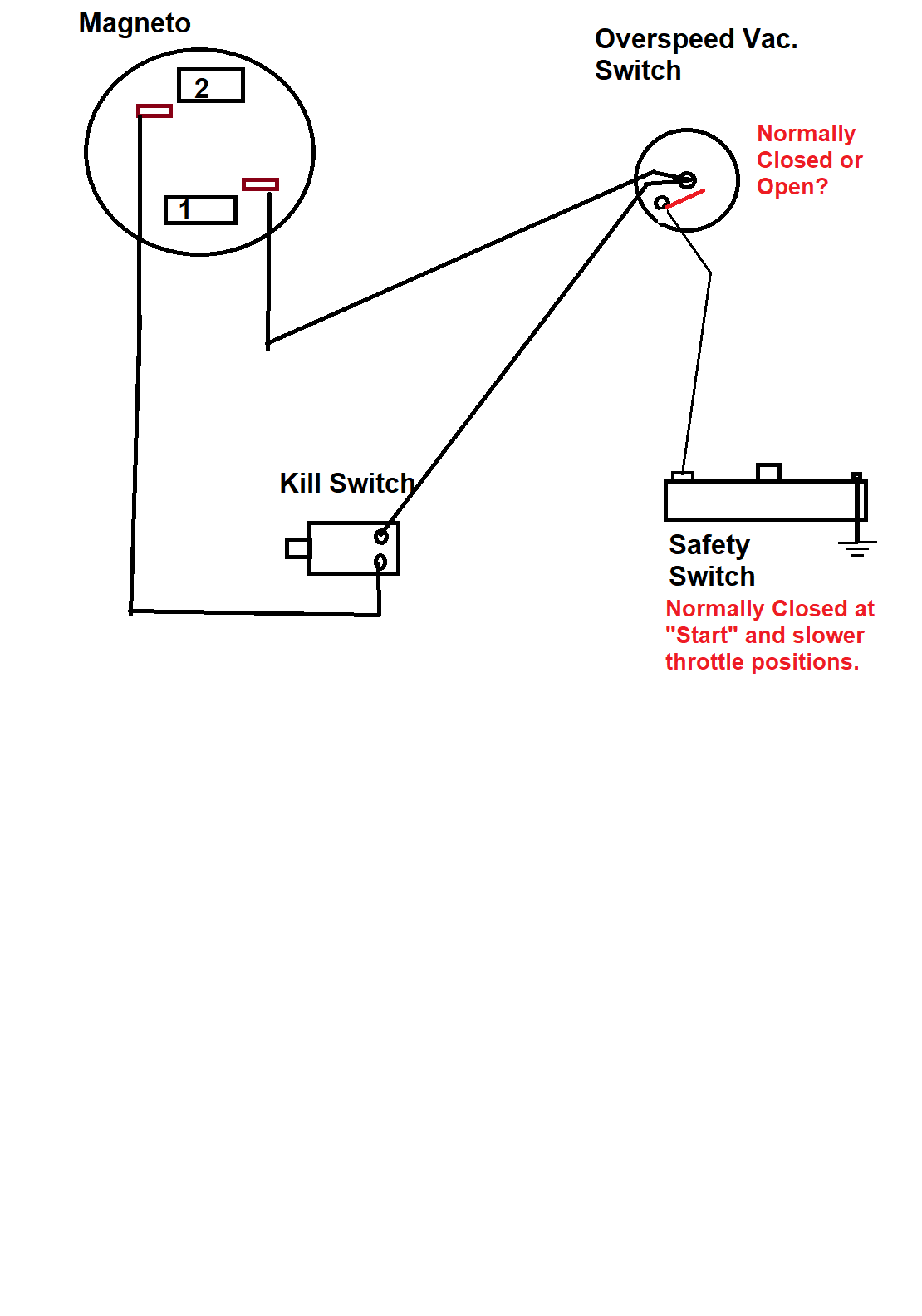
work together.I presume the vacuum switch is “normally open” and “closes” at high vacuum occurrences
to prevent the engine from “running away”. ???
Are the two wiring post on the vacuum switch a connection across the internal contacts
when the vacuum switch “closes”. I did not test this switch to learn how it functions.
Will try tomorrow, but I don’t have a vacuum pump.The fuel saver rod may or may not be set correct. I did not understand it at first until
I discovered that the spring “snapped” the throttle full open once the control arm reached
a certain position. Then I noted that one could “throttle down” some with the magneto
remaining in full advance. Isn’t that the idea???Frank, it looks like you are correct regarding the kill switch wiring going under the coils,
after reviewing the photo when I finally got the flywheel off……. by destruction. 🙁
Thanks!
Prepare to be boarded!
October 28, 2019 at 11:40 pm #186069I spent a half hour on a reply to you two, but lost the whole
thing in an edit. Will try again tomorrow….. getting too tired out!
Thanks!Prepare to be boarded!
October 29, 2019 at 8:57 am #186072A new day, so I’ll try my response again, and hopefully not
have to edit and lose it all.Regarding the Safety Switch. In testing it yesterday,
I found that it was “closed” at “Start” position and
slower speeds. Is the Safety Switch the evolution
of the prior mercury switches that prevent starting
above “Start” speeds?I did not test the Over-speed Vacuum switch, but will
do what I can today, although I don’t have a vacuum
pump. I presume the switch is “normally open” and
“closes” only during high vacuum occurrences?
Are the center and lower left wire post contact
points across the internal switch?With all the above assumptions, I still don’t understand
the “logic” on how the two switches work together. HELP!Frank, after looking at the photo of the original
coils, I see you’re correct, the kill switch wires
did go under the coils. Guess I’ll have to backtrack
a little there.Regarding the Fuel Saver Rod, it may or may not be
adjusted correctly, but I went by the book, albeit
for a similar looking 40 hp Johnson, not a Gale.
I didn’t understand how it worked, until I realized
the throttle “snapped” into full speed position
at a certain point, and then one could back off on
the throttle some and have the magneto remain at
full advance. Is this the idea?Thanks again!
Prepare to be boarded!
October 29, 2019 at 12:48 pm #186082Yes, safety switch is closed at “Start” and slower
Yes, an evolution from the old mercury switdhes
Yes vacuum cutout is normally open, closes at high vacuum
Yes, center is one side of the switch, case (lower left) is other side of switch
At high RPM under no-load condition such as neutral or lost prop, etc, a high intake manifold vacuum is created. That is applied to the switch which closes and shorts one cylinder to the case. But since the switch is mounted on plastic it is not grounded. Enter the safety switch. It provides a ground return for the cut-out switch. BUT only at slower throttle settings. Reason: at certain speeds and loads such as cruise throttle, the vacuum switch might close when not required, providing a hard to diagnose high speed miss. The safety switch disables the cut-out switch at high throttle settings.
Yes your understanding of the fuel saver / cruise throttle is correct
October 29, 2019 at 1:26 pm #186087Frank, thank you kindly for the time and explanation of the system.
Everything makes sense in what you said, but what I’m not getting now
is regarding the Safety Switch and how if prevents starts at “above start”
throttle settings.
If the Vacuum switch is “normally open”, how is the safety switch preventing
starts at high throttle positions? I don’t see how it could ground out either coil.
Thanks.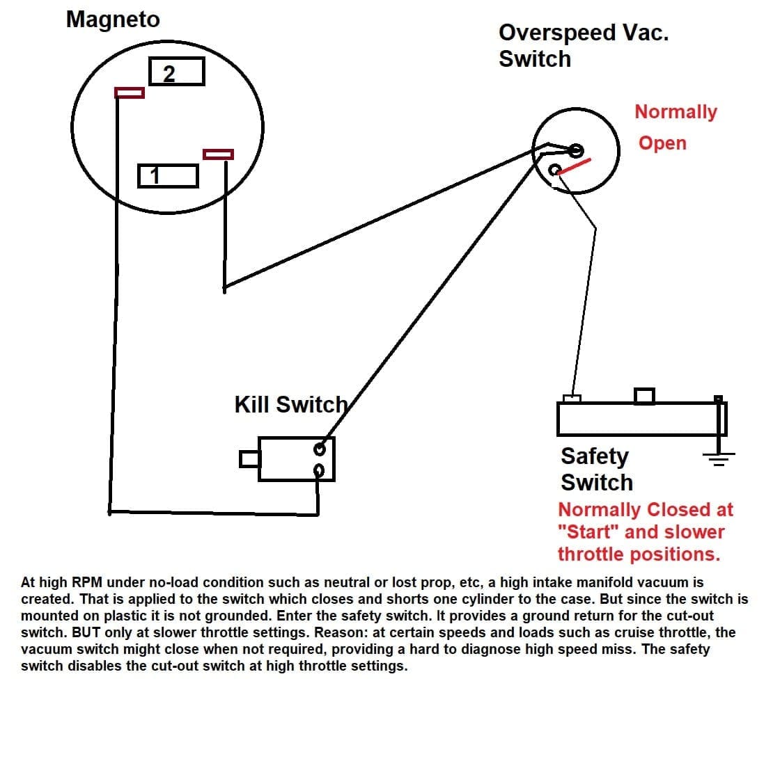
Prepare to be boarded!
-
This reply was modified 6 years, 7 months ago by
-
AuthorPosts
- You must be logged in to reply to this topic.