Home › Forum › Ask A Member › Early Johnson Plunger for Pump
- This topic has 10 replies, 5 voices, and was last updated 4 years, 6 months ago by
davidk.
-
AuthorPosts
-
December 19, 2021 at 10:41 pm #251397
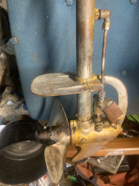
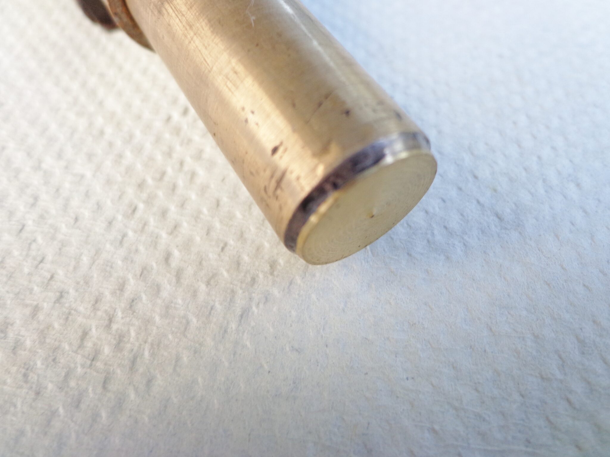
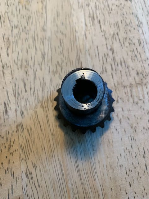
This is a water pump from a Johnson DN. The plunger is worn, but not all the way through. What’s the fix? Probably have to find another, maybe under a pile of hen’s teeth?
As these plungers wear down, they must pump less water, right? I wonder if that’s why a prior owner put that “scoop” on there?
 December 20, 2021 at 9:14 am #251410
Even though the piston is worn its the cam that
controls its stroke so piston wear doesn’t reduce
the volume of water. Problems arise when a
hole is worn through the piston. Depending
on how much you plan on running it, its
probably OK as it is. If you get to the point
where you have a hole, the Buccaneer would
just make a new piston. A boat house repair
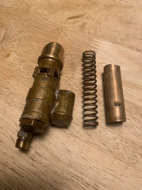
would be to file the piston flat, take a piece of
thick wall copper tubing, cut it open, hammer
it flat. Shape it to the size of the piston and
solder it on, if I couldn’t find anyone to make
me a new piston.
TubsA "Boathouse Repair" is one thats done without having tools or the skills to do it properly.
December 20, 2021 at 1:51 pm #251437Thanks for the reply, Tubs. I was thinking a shortened piston would pump less water. Not sure where I got that calculus?
I appreciate your suggestion that it might be fine just to keep using it for as infrequently as I might run it.
All kinds of mystical things can happen in that boat house!
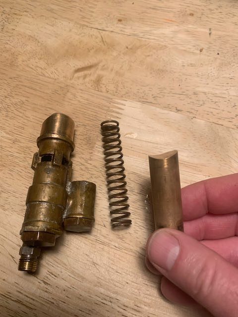
December 20, 2021 at 11:25 pm #251491I’d suggest that you at least go to the trouble of figuring out how thick the bottom of the plunger still is. Rudimentary measurement using the depth rod on a dial caliper would more than suffice. It might have sufficient material left, it might be paper thin. You at least want to know what you have.
Hope it helps.
Best,
PM T2He's livin' in his own private Idaho..... I hope to go out quietly in my sleep, like my grand-dad did..... and not screaming, like the passengers in his car...
December 21, 2021 at 8:41 am #251495Thanks PM-T2, that’s a good suggestion and only requires
rudimentary skills. : )-
This reply was modified 4 years, 6 months ago by
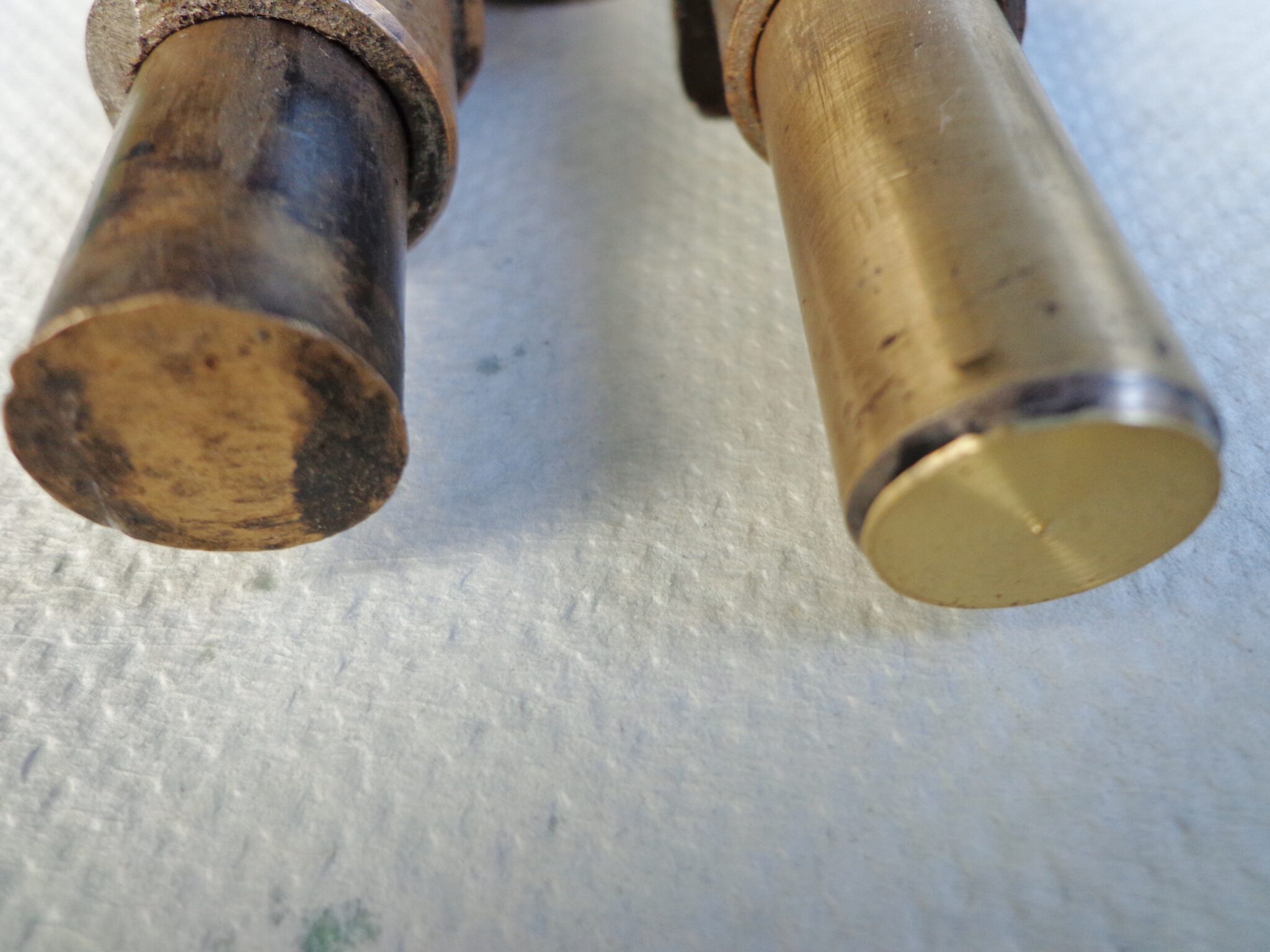
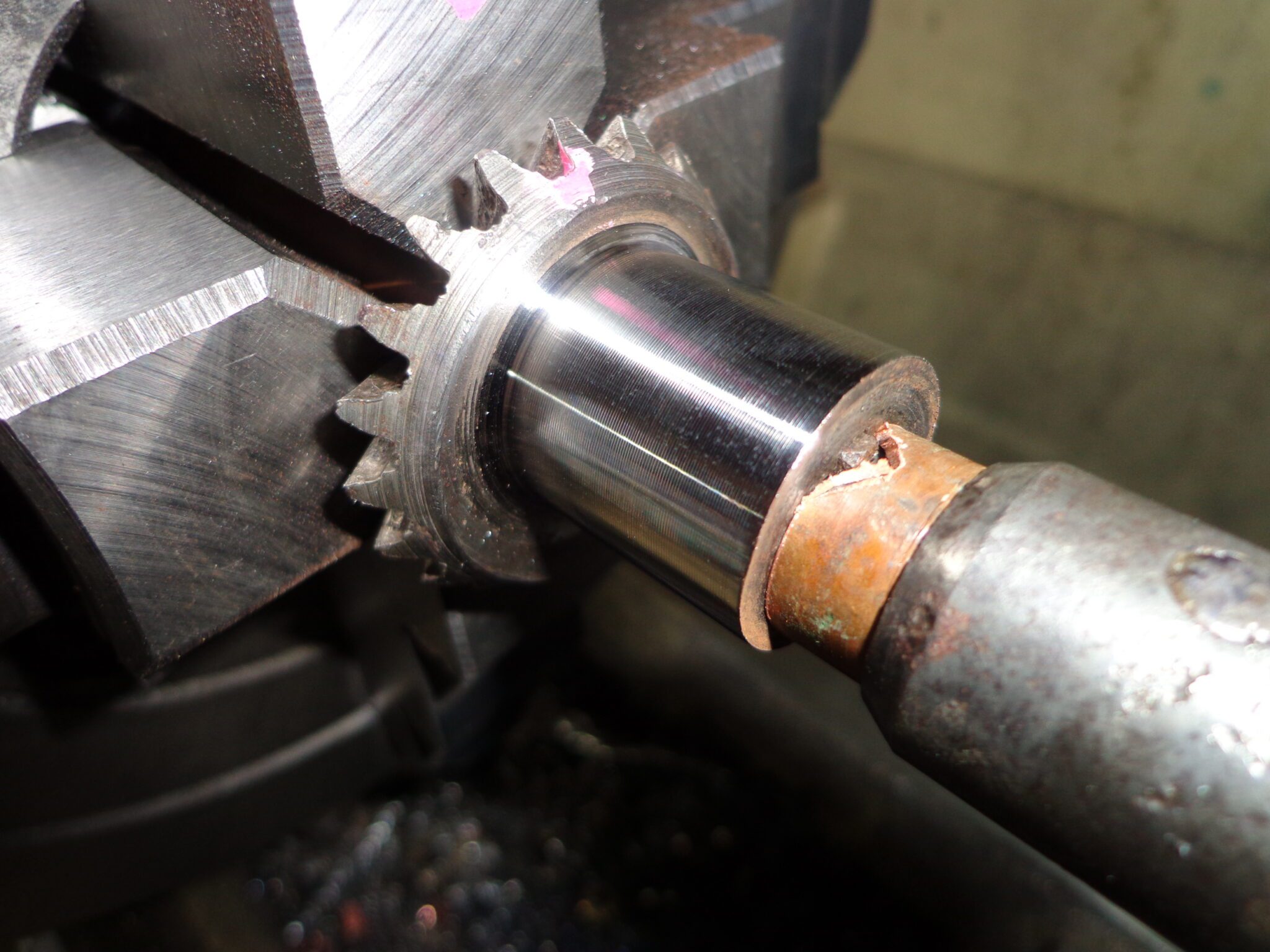
December 23, 2021 at 3:59 pm #251620On a couple pumps I squared off the end of the worn piston and silver soldered a flat piece of brass onto it. I thought about using a penny but copper might be too soft. The worn and damaged cams got reprofiled to and the thickness of the brass piece allowed for what was removed from the cam and the piston. The piston height and stroke remained the same as stock.
 December 23, 2021 at 9:07 pm #251651
Nice work, Mumbles! I can see that it was essential to reprofile that cam or it would have been a grinder on the repaired plunger. Thanks for the photos and explanation.
-David1 user thanked author for this post.
December 24, 2021 at 12:43 am #251660Brilliant work Mumbles on that cam!……..the photos are excellent too…..well done!
Monte NZ
1 user thanked author for this post.
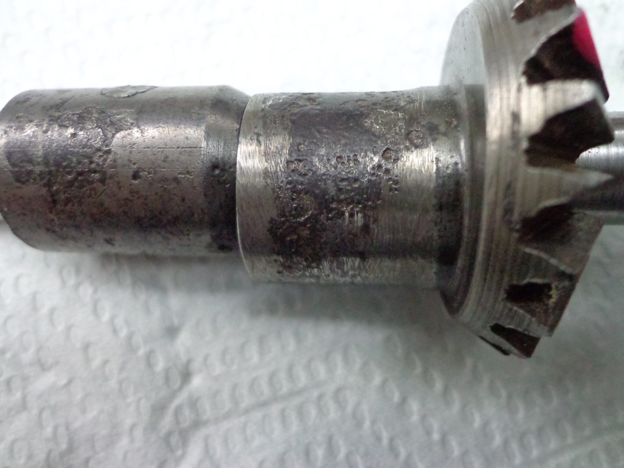
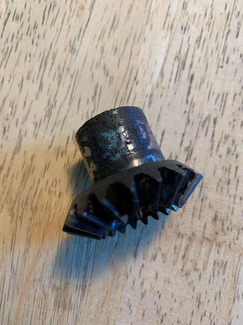
December 31, 2021 at 10:13 am #252020Here’s the cam from the DN. Looks corroded. Mumbles, I’m wondering how you were able to turn yours to clean it up when the cam is …..off center? I suppose it’s the shaft that’s off center, but, you probably get what I’m asking.
 December 31, 2021 at 11:50 am #252032
The gear is centred to the shaft but the lobe is off. This is where the four jaw chuck and a dial indicator are used to centre the axis of the lobe. If you don’t have a four jaw, one jaw in a three jaw chuck can be installed one turn of the scroll out of synch of the other two. This will give a rough non adjustable offset but shims can be placed under the teeth of two of the jaws to get a finer adjustment.
The prop shaft wasn’t threaded on either end so I used a rotating chuck in the tailstock to keep pressure on the cam while it was being turned. The piece of copper tubing in my last photo was used to get the clearance needed to get a good unobstructed cut.
-
This reply was modified 4 years, 6 months ago by
-
AuthorPosts
- You must be logged in to reply to this topic.