Home › Forum › Ask A Member › Evinrude, early two stage metal water pumps
- This topic has 2 replies, 2 voices, and was last updated 4 years ago by
 Buccaneer.
-
AuthorPosts
-
July 2, 2022 at 7:12 pm #262370
I got to pondering about the subject matter metal water pumps,
and was wondering if they are intended to be “set up” for any certain
clearance between the second stage impeller and pump plate?
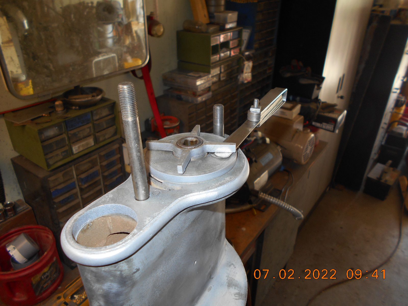
As it is, the impeller drags on the plate when rotated. To raise the impeller
off the plate, the stub drive shaft would have to be be jacked up with
shims inside of the bronze piece it rides in, in the gear case.
The impeller lifts up probably .060 before the first stage impeller
hits the bottom side of the pump plate.
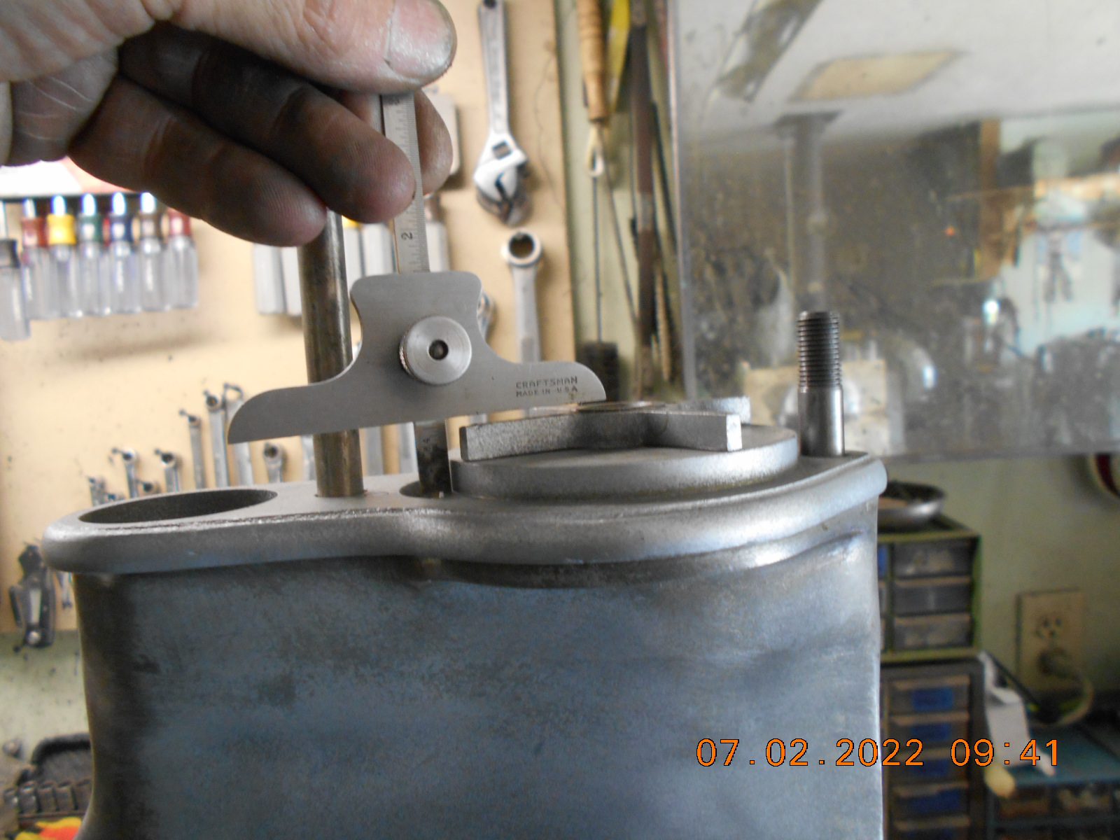
The depth gauge represents the pump housing height, and there’s
ample room to raise the impeller if necessary.
I would think if the impeller is as close to the plate without rubbing,
would be the most efficient.
I don’t remember ever seeing anything about this in a manual, but
will look tonight. Any thoughts?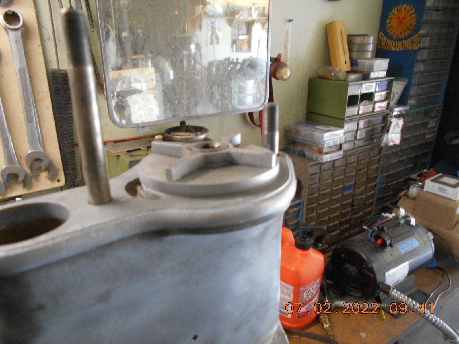
Prepare to be boarded!
July 3, 2022 at 6:05 am #262385On most gear cases, when they start to operate, the gears want to try to move apart. In modern gear cases, where the pinion gear is fastened to the drive shaft, the whole drive shaft lifts up. I’m not that familiar with your gear case but I am wondering if maybe that is designed to happen in yours, too? That might lift the impeller to a good operating height?
Long live American manufacturing!
July 3, 2022 at 7:37 am #262388Bob, I thought about your idea, but I don’t see how the centrifugal gear force
could move this driveshaft “up” while running.
The drive gear is keyed on the driveshaft, then a trunion like affair slides over
the end of the driveshaft, and is fixed upon the prop shaft.
I’m not sure if the driveshaft can be shimmed higher inside of the trunion or not.
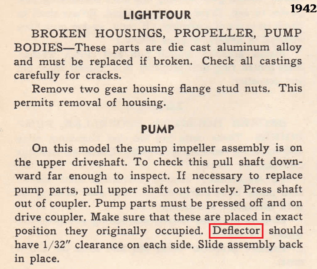
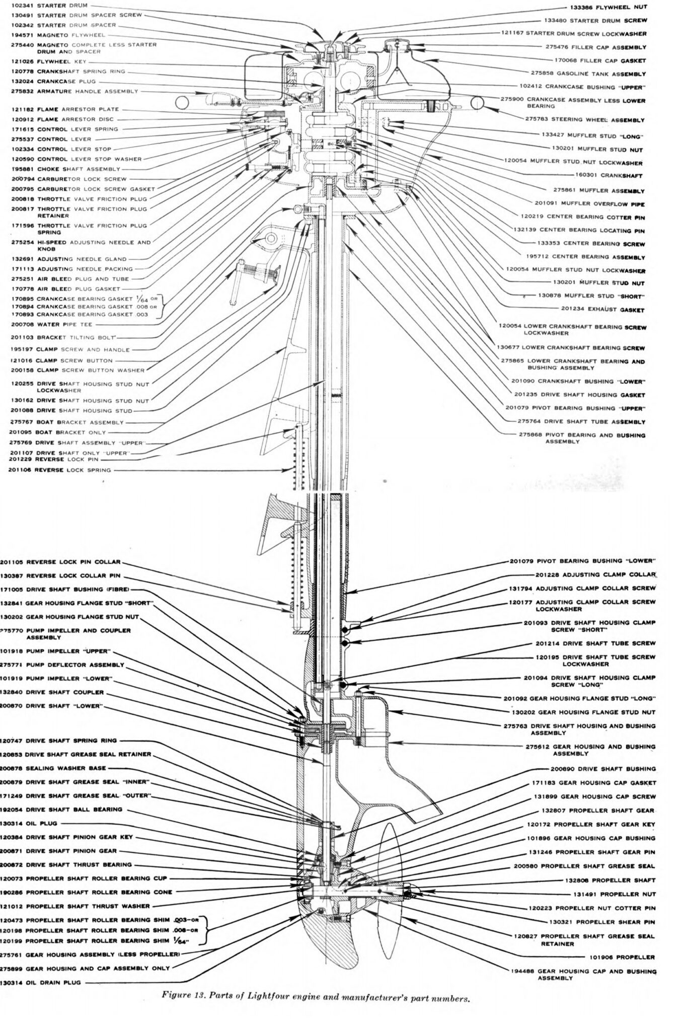
The only shims I see mentioned in the parts diagram is for the prop shaft end play / gear mesh.I did find mentioned in the 1942 Evinrude repair manual, a paragraph on the two stage
style metal water pump impellers, stating that the “Deflector” should have 1/32″ clearance
on each side. I presume the “deflector” is the plate that separates the upper and lower impeller.
I gather from what the paragraph is saying, that this clearance is in regards to when the upper
and lower impellers are being pressed together, not any “setup” after the fact.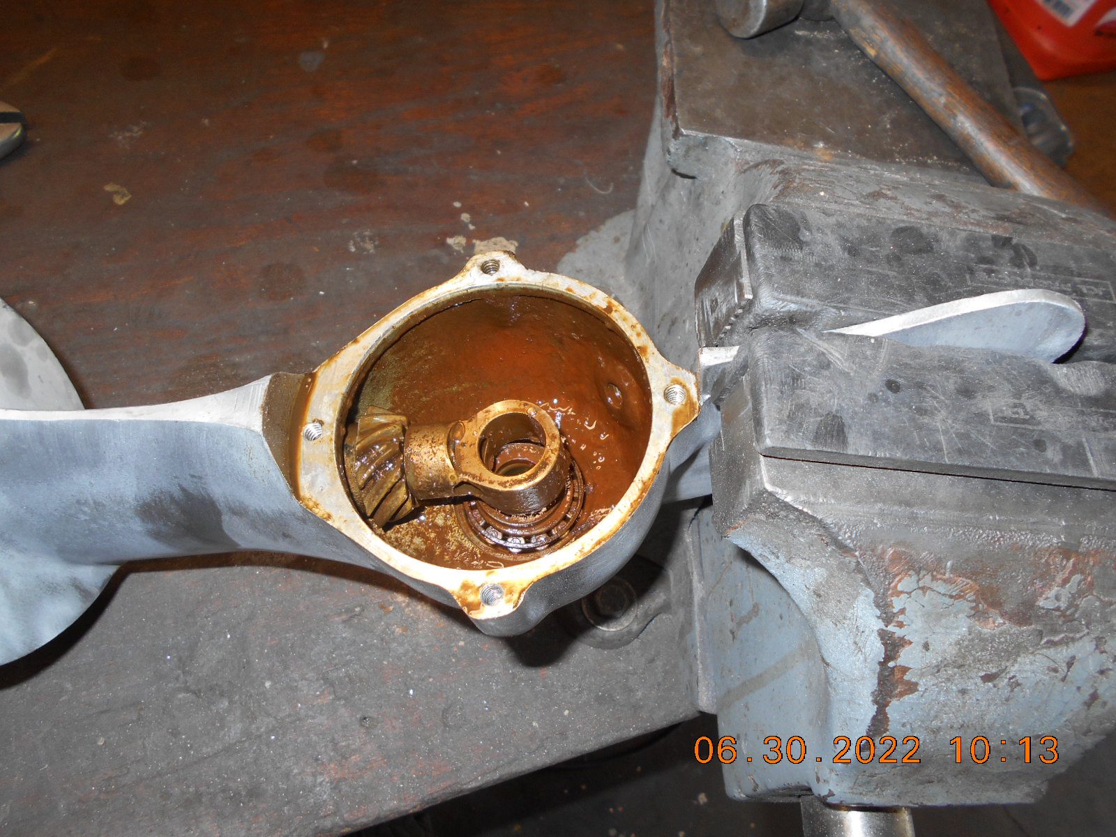
Prepare to be boarded!
-
AuthorPosts
- You must be logged in to reply to this topic.