Home › Forum › Ask A Member › Installing clutch dog in 1950’s OMC lower unit
- This topic has 6 replies, 3 voices, and was last updated 3 months, 1 week ago by
JACQUES.
-
AuthorPosts
-
March 13, 2026 at 11:06 am #308975
Hello. The clutch dog in the lower unit in 1950’s OMC Johnson / Evinrude can be installed either way, but recently someone told me that there is a correct way to install them. Is this true? I was told there is a mark or ring on one side that should face the forward gear. Thank You. Bill,
March 13, 2026 at 12:26 pm #308994download this book it hasall you need to service oldies see section on lower unit pages 389 390 pictures
https://www.socalaomci.com/library/johnson_service_manual_10th_edition.pdf
Joining AOMCI has priviledges 🙂
March 13, 2026 at 1:39 pm #309011Thanks Frank!
5 users thanked author for this post.
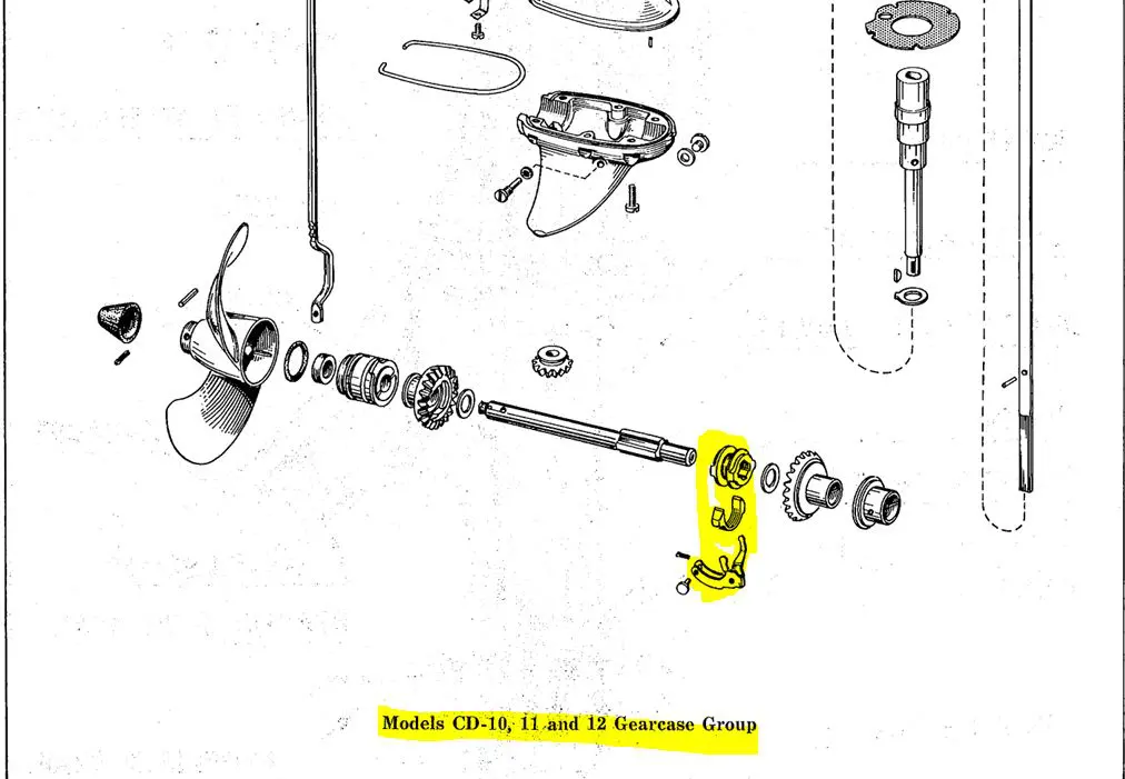
March 13, 2026 at 2:13 pm #309021cd 10-11-12 specific picture
Joining AOMCI has priviledges 🙂
March 14, 2026 at 2:05 am #309149Thanks Frank!
So, the takeaway from this is that it is noted but really it can go either way. With no ill effects.
March 14, 2026 at 6:47 am #309183That’s correct. Usually the practice is to make sure the better side is engaging with the forward gear since that gets used more.
1 user thanked author for this post.
March 14, 2026 at 7:50 am #309188btw if op is inside the GC fixing up things may as well confirn the shock absorber has not stretched beyond 6”11/16 otherwise .
when i did mine i had a heck of a time closing up the GC and after 2-3 reseals I found mine had somehow streched and rubbed the underside of the wp enough to cause binding problems. Had it spot welded shut, filed the weld burs away and resealed the GC. Pressure tested fine after and… no more binding on the drive shaft
- Correct length: about 6 11/16″ (6.69″)
- If it stretches to ~6 3/4″ (6.75″) or more, it can start rubbing or binding in the housing.
- These shock couplers often stretch after the prop hits something; sometimes they can be pressed shorter again in a vise if not broken.
What the shock absorber does:
- It’s a spring coupler in the driveshaft that absorbs impact if the prop hits a rock or log.
- If it’s too long, the shaft can bind.
- If it’s welded solid, you lose that protection and risk damaging the gears so using a brass drive pin helps
Joining AOMCI has priviledges 🙂
1 user thanked author for this post.
-
AuthorPosts
- You must be logged in to reply to this topic.