Home › Forum › Ask A Member › Starter Solenoid Wiring
- This topic has 20 replies, 6 voices, and was last updated 1 month, 1 week ago by
 Bob Wight.
-
AuthorPosts
-
April 5, 2026 at 4:08 pm #314169
OK, I have verified Don’s explanation of how it works. The neutral switch does go to ground through the switch mounting bracket when the gearshift is in neutral, thus providing the ground connection to the starter solenoid. I tested the operation of my neutral switch and it is working correctly – the switch shows zero resistance with the switch plunger depressed like it would be with the motor in neutral.
I realized that in all my motor restorations, this is the first one I’ve done with factory electric starting and charging, so I don’t quite fully understand everything I know about it yet! Glad I had the help of everyone here or I could have really made a mess of things!
Bob
1937 Champion D2C Deluxe Lite Twin
1954 Johnson CD-11
1955 Johnson QD-16
1957 Evinrude Fastwin 18
1957 Evinrude 3022
1958 Johnson QD-19
1958 Johnson FD-12
1959 Johnson QD-20
1982 Evinrude 25hp“Every 20 minute job is only a broken bolt away from a 3-day project.”
"Every time you remove a broken or seized bolt an angel gets his wings."April 6, 2026 at 8:35 am #314297Usually the starters just need to have their brushes/commutator cleaned up, and a little lube added to the shafts/helix. I wouldn’t replace that switch and solenoid unless you check them out and find problems. You could replace all this stuff and still have a problem if the wiring/cables/connections have issues. Once again, someone did some home made wiring on this engine, so who knows exactly what is going on. Some engines have a main 20 amp fuse, but I don’t think the tiller electric models had this feature.
April 6, 2026 at 11:17 pm #314410Don – The push-button start switch is corroded to the point it’s not worth trying to save. I haven’t opened up the starter yet but when I removed it from the mounting bracket, the long bolts were also badly corroded and when turning the pinion by hand, it sounds very crunchy inside the housing. I’ll open it up sometime in the next few weeks as I progress through the restoration. The solenoid did check out OK today so I can re-use that.
All of the wiring harnesses on the motor and shown in my pictures are factory correct – the only homemade work was some type of auxiliary wiring somebody rigged up to tie into the engine-mounted start switch and kill switch to control them remotely. I took that out on day one, leaving only the factory correct work.
Thanks again for your help on this.
Bob
1937 Champion D2C Deluxe Lite Twin
1954 Johnson CD-11
1955 Johnson QD-16
1957 Evinrude Fastwin 18
1957 Evinrude 3022
1958 Johnson QD-19
1958 Johnson FD-12
1959 Johnson QD-20
1982 Evinrude 25hp“Every 20 minute job is only a broken bolt away from a 3-day project.”
"Every time you remove a broken or seized bolt an angel gets his wings."April 7, 2026 at 8:12 am #314437Sounds great, I just didn’t want you to spend big bucks for all new parts only to still have an issue. The starter buttons shouldn’t be too expensive. I’m glad you yanked off all the home made wiring stuff.
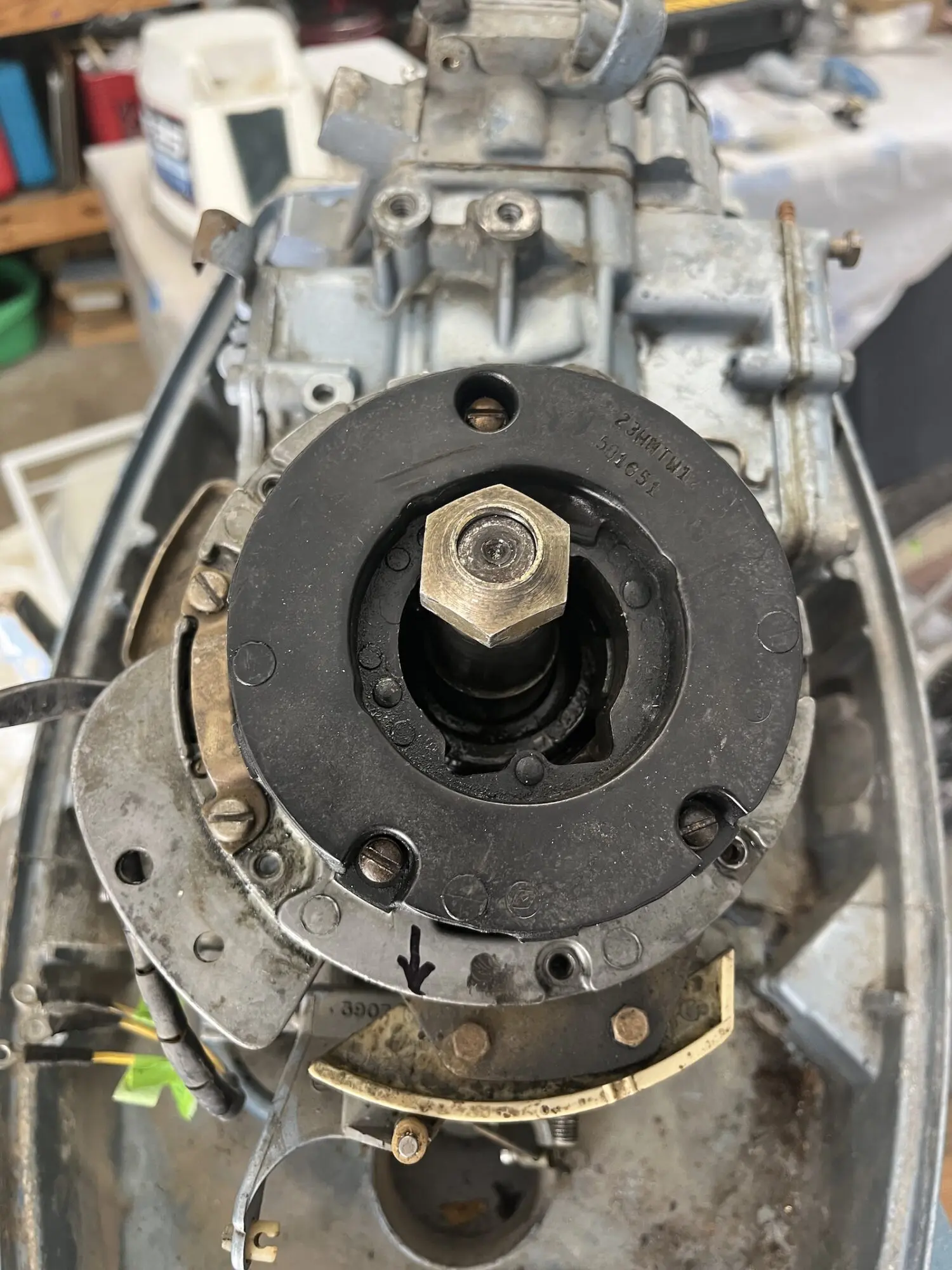
April 7, 2026 at 3:47 pm #314491OK, next question. As part of the motor tear-down I pulled the flywheel and found the stator assembly (it looks a little cocked to the front in this picture because I had already loosened the stator assembly from its retaining plate below).
I’ve looked at several online parts diagrams for this motor (model E25RCNB) and the diagrams all show a charge coil and ignition sensor as part of this ignition system, with both of those pieces mounted to the same plate as the stator. I don’t see any such charge coil or ignition sensor on mine, I don’t see any way those pieces could mount on the stator plate and I don’t see any loose wires or connections where the charge coil or ignition sensor could hook up to.
When I first got the motor, I checked it for spark and it was throwing a really hot blue spark on both plugs. So what do I have here?
EDIT – OK, think I got it now. A little more research would indicate the separate charge coil and ignition sensor components can be used together as an upgraded replacement for the older stator assembly with integral charge coil and sensor that I have on this motor . I’m learning as I go – any further input is always welcome, especially if I’m wrong!
Bob
1937 Champion D2C Deluxe Lite Twin
1954 Johnson CD-11
1955 Johnson QD-16
1957 Evinrude Fastwin 18
1957 Evinrude 3022
1958 Johnson QD-19
1958 Johnson FD-12
1959 Johnson QD-20
1982 Evinrude 25hp“Every 20 minute job is only a broken bolt away from a 3-day project.”
"Every time you remove a broken or seized bolt an angel gets his wings."April 7, 2026 at 10:34 pm #314543OK, well that stator sure seems out of whack…But, the flywheel would never fit over it if the stator was that far out of center.
That stator is really three separate windings encased in potting. The two styles of mag plates can be interchanged. The “charge coil” is actually an ignition component that develops several hundred volts AC to charge up the capacitor in the powerpack. The “sensor coil” is another ignition component that “triggers” the powerpack to release stored voltage to the coils. The alternator windings provide AC voltage that is rectified externally to help charge the battery.
April 8, 2026 at 12:28 am #314549Don – thanks for the continued education. It’s been a big help in my understanding of how this thing works.
Bob
1937 Champion D2C Deluxe Lite Twin
1954 Johnson CD-11
1955 Johnson QD-16
1957 Evinrude Fastwin 18
1957 Evinrude 3022
1958 Johnson QD-19
1958 Johnson FD-12
1959 Johnson QD-20
1982 Evinrude 25hp“Every 20 minute job is only a broken bolt away from a 3-day project.”
"Every time you remove a broken or seized bolt an angel gets his wings."April 9, 2026 at 10:24 am #314688Don – thanks for the continued education. It’s been a big help in my understanding of how this thing works.
Glad to help. These ignition/electrical systems are pretty basic, and easy to understand once you see the wiring diagram and have a basic understanding of how the CDII ignition system works.
That crankshaft sure seems off center though, judging by your picture! But, this must be some sort of photo illusion, the flywheel would never fit in place if things were that “out of whack”. OK, just looked at the photo again…. Looks like you have all the phillips mag plate retainer screws removed, so the mag plate probably just isn’t sitting in the proper position..
Be sure to replace that plastic mag plate bushing: 322435. Check the mag plate for sideways slop in the crankcase pilot busing. Be sure to relube that pilot bushing properly with OMC moly lube, give the new plastic bushing a light coating of two stroke oil as well.
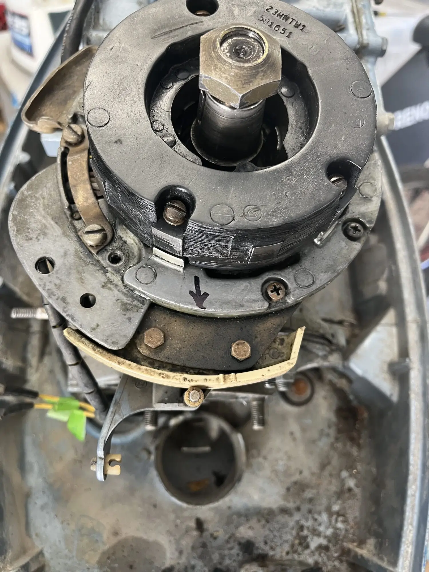
April 9, 2026 at 8:13 pm #314776That picture is misleading – I had already removed the stator from the retainer plate below and just pulled it up and forward a bit to take the picture. The stator is not off-center from the crank! Here’s another pic taken before I pulled the stator off the retainer plate.
I have found another wiring diagram for this motor and have been reading up on the ignition system so I could get a better understanding of how it works – pretty straightforward.
Thanks for the tip on the mag plate bushing. Somebody had been into this thing before me – between the upper crank seal leaking and the liberal amount of grease they had slathered onto the bushing, it was one big mess. Over the years the motor sat idle, the grease had hardened up into something resembling stiff molasses. Here’s a pic showing how I found it – it’s all cleaned up now but I will replace the plastic bushing.
Bob
1937 Champion D2C Deluxe Lite Twin
1954 Johnson CD-11
1955 Johnson QD-16
1957 Evinrude Fastwin 18
1957 Evinrude 3022
1958 Johnson QD-19
1958 Johnson FD-12
1959 Johnson QD-20
1982 Evinrude 25hp“Every 20 minute job is only a broken bolt away from a 3-day project.”
"Every time you remove a broken or seized bolt an angel gets his wings."April 10, 2026 at 1:50 pm #314909Glad you got that mag plate cleaned and lubed. Once the engine block/mag plate pilot bushing is worn, there is really no fix other than to replace the mag plate and the engine block!
Happy you found a wiring diagram also, the ignition system is really pretty simple. And the charging system makes sense once you see a flow diagram of how the AC voltage from the windings through the recitifier.
You may want to find an OEM service manual for this engine, basic theory is discussed as well as wiring diagrams.
-
AuthorPosts
- You must be logged in to reply to this topic.