Home › Forum › Ask A Member › V4 cooling schematic?
- This topic has 9 replies, 3 voices, and was last updated 7 years, 11 months ago by
 frankr.
-
AuthorPosts
-
July 30, 2018 at 2:56 pm #10714
I’ve been working on a 1970 85 hp V4 ,which is, I hope, about ready to go. I’ve seen no indication of cooling problems, but I don’t really understand how the system works, and in particular how the temperature control setup works. None of my manuals, or info found online, is clear. Also, opinions on how to install a telltale(s) are variable.
Could anyone point me to the best publications on this, or post a couple of relevant pages?
Thanks much.
Alan
July 30, 2018 at 3:14 pm #80390I’ll look and see if I have the OEM service manual for this engine, which is the best place to see an accurate cooling system diagram.
Later models had the telltale tapped into the outer exhaust cover. But, your cover does not have the boss in place to drill and tap for the elbow. I hesitate to advise trying to drill and tap into your existing cover, I fear you may drill through the inner exhaust cover as well.
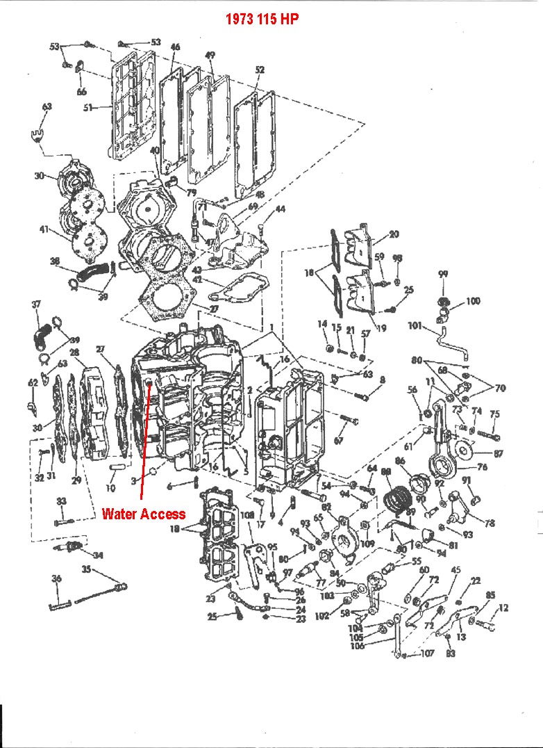
Have you replaced the water pump on this engine lately, or is it new to you? Is it a fresh or salt water engine?July 30, 2018 at 4:25 pm #80392That motor has a thermostat controlled recirculating cooling system. Water from the pump circulates through the powerhead and is then presented to the thermostat. If the ‘stat says it is too cool, the water pushes through the relief valve next to the ‘stat valve and returns to the water pump for recirculation. When the ‘stat decides it is warm enough it opens the discharge valve and the water is discharged and replaced with cool lake water. This is not an either-or thing. The ‘stat is constantly sampling the water and opening or closing as necessary to maintain desired temperature. A slot in the discharge valve allows a bit of water to discharge even if closed. This is necessary in order to cool the exhaust and provide a visual discharge out the exhaust relief hole.
There is a convenient place to access the water if you insist on seeing it pee. The port is blanked off from bygone days when they had a hot water choke. Drill & tap 1/8 NPT and screw in your hose fitting.
 July 30, 2018 at 5:40 pm #80400
Impeller was replaced. Still has the original style aluminum pump housing but it seemed in usable condition. I think I need to drop the gearcase again, though, as when I put it on I didn’t know how to use the plastic sleeves to ensure the two water tubes are properly in the pump.
No sign of any sort of telltale on this motor, but there was an undrilled boss on the #1 cylinder water jacket. Maybe originally for a choke heater or? It’s about an inch below the top of the water jacket so not ideal, but I tapped it for a fitting. Anybody think it worthwhile to drill and the real top of the water jacket? I could do it safely with stops on the drill.
Alan
Note: I wrote this before seeing Frank’s response. Thanks!
July 30, 2018 at 5:45 pm #80401OK, so the box under the electrical panel is the "thermostat housing," and contains the ‘stat, the pressure operated valve, and various springs and widgets and gaskets. Looks like I could either (1) dismount the electrical panel and take the top off, or (2) remove the two mounting screws and pull it back. Which is best? Or is it safe to leave it alone?
I forgot to say: Fresh water motor here.
July 30, 2018 at 7:34 pm #80409Well, the good news is that the screws holding the cap the thermostat cover thread into the plastic housing and don’t seem to ever get rusted in place. I would pull the electrical panel out of the way, or maybe just removing the power pack would give decent access to the screws.
July 31, 2018 at 1:21 am #80438quote fleetwin:Well, the good news is that the screws holding the cap the thermostat cover thread into the plastic housing and don’t seem to ever get rusted in place. I would pull the electrical panel out of the way, or maybe just removing the power pack would give decent access to the screws.Took the panel loose, which was easy. Found one of the cover bolts underneath had backed out, so it was worthwhile for that alone.
Cover screws on tst box came out with no resistance as you predicted. It’s pretty clear from the intact paint film that they’d not been out since the the motor was built up. BUT, the cover is stuck on solidly and I’m afraid to pry on it very hard. After all, the whole thing IS plastic and almost fifty years old at a minimum. So I stopped to think about it.
July 31, 2018 at 12:06 pm #80458Yeah, you don’t want to crack that plastic for sure….Maybe a razor knife gently inserted into the gasket surface? It is probably best to just replace that vernatherm while you are inside the box, make sure the check valve is clear of debris and working properly….
Frank pointed out a good spot for the overboard indicator tap. I seem to remember that your control box only has a "hot light", instead of the "hot horn". You might consider adding the hot horn inside the box if possible. This will be very easy if your rig has dash mounted key switch and wiring.
Once you have the gearcase off, you will probably see that the plastic water tube guides that have slid upwards on the water tubes….July 31, 2018 at 6:51 pm #80474quote fleetwin:Yeah, you don’t want to crack that plastic for sure….Maybe a razor knife gently inserted into the gasket surface? It is probably best to just replace that vernatherm while you are inside the box, make sure the check valve is clear of debris and working properly….I got it open and all seems well. The vernatherm seems to open and close smoothly using the usual saucepan-of-boiling-water method. But of course it’s not a complete thermostat but just the thermal element. Would you still suggest replacing?
Frank pointed out a good spot for the overboard indicator tap.
That’s drilled and tapped.
I seem to remember that your control box only has a “hot light”, instead of the “hot horn”. You might consider adding the hot horn inside the box if possible. This will be very easy if your rig has dash mounted key switch and wiring.
The control box I’m using has a horn, but I haven’t tested it yet.
Once you have the gearcase off, you will probably see that the plastic water tube guides that have slid upwards on the water tubes….
Yes, they are there, I just didn’t know how to use them. I really need to get a factory manual for this motor.
Alan
July 31, 2018 at 8:26 pm #80475Stick the guides in the pump outlet holes. That’s what they are–guides. You can see to enter the tubes into the guides, but it is impossible to see to enter the tubes directly into the pump without the guides.
-
AuthorPosts
- You must be logged in to reply to this topic.