Home › Forum › Ask A Member › Which nipple was used for the double hose pressure tank?
- This topic has 14 replies, 7 voices, and was last updated 7 years, 5 months ago by
 outboardnut.
-
AuthorPosts
-
January 26, 2019 at 8:38 am #164797
A bit embarrassed about this one but I here go.
I am in the process of converting from a double hose pressure tank system to a single line tank system.
One nipple is for the vacuum switch the other is (was) connected to the double line fuel pressure tank.
One of the steps in the conversion is to plug the nipple that went to the pressure tank.
I forgot which nipple it was.
Did the nipple with the red arrow or the yellow arrow go to the double line tank?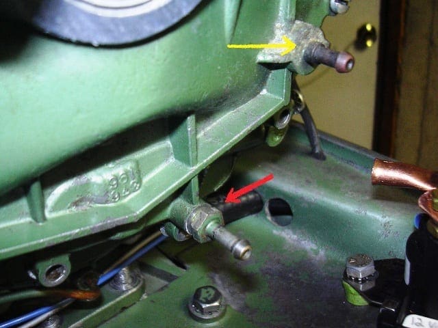
-
This topic was modified 7 years, 6 months ago by outboardnut.
-
This topic was modified 7 years, 6 months ago by outboardnut.
January 26, 2019 at 9:35 am #164815Is this the same?
Prepare to be boarded!
January 26, 2019 at 9:41 am #164818the motor in question is a RDE-17 Johsno 1955
 January 26, 2019 at 9:50 am #164820
I’m pretty sure it is the lower one but you might want to check it by giving it the suck and blow test by placing a piece of tubing on it and trying to blow into it. The check valves inside should prevent air from entering but allow air out. The other one must be manifold vacuum for the cutout switch and should pass air both ways.
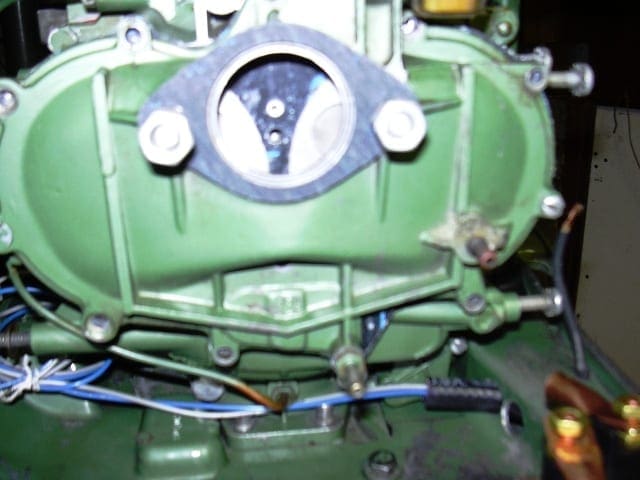
January 26, 2019 at 10:11 am #164821Unfortunately I took out the check valves and sealed the channel with 847 to do the conversion.
This picture is from a different motor.It just shows what I did on my motor but neater lol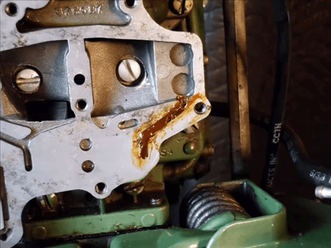
-
This reply was modified 7 years, 6 months ago by outboardnut.
-
This reply was modified 7 years, 6 months ago by outboardnut.
-
This reply was modified 7 years, 6 months ago by outboardnut.
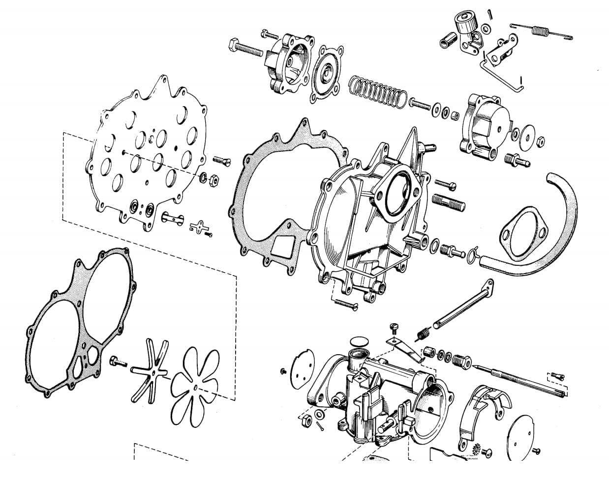
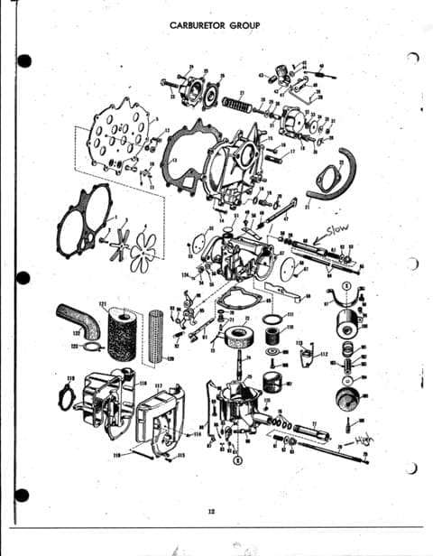
January 26, 2019 at 10:40 am #164829?? I am missing something here .. doesn’t the parts diagram show the side nipple feeding the cut out switch ?
and if the check valves are out and one channel plugged that becomes the pulse nipple subject to in and out movement of the remaining cyl feeding the open channel pushing air and vacum via the back plate of the carb
a blow test should allow air in and out no ?
Joining AOMCI has priviledges 🙂
January 26, 2019 at 11:48 am #164833In your first picture, the red arrow points to the pulse line for your fuel pump conversion (passes air both directions after the conversion). The yellow arrow goes to the vacuum cut-out switch.
Now that you’ve gone to all that trouble, that is not the preferred way to do it in my opinion. Far easier to get the pulse from one of the bypass covers. But proceed anyway.
January 26, 2019 at 12:12 pm #164838I hooked up a fuel pump to the bypass cover
One side of the pump will go to the tank
The other side of the pump will go to the carb
Per Franks statement
I will block the nipple with the red arrow with a vacuum cap or take out nipple and put a screw in or solder it closed
The nipple with the yellow arrow will go to the vacuum switch
I believe that is correct.
What I needed to know was which nipple was for the vacuum switch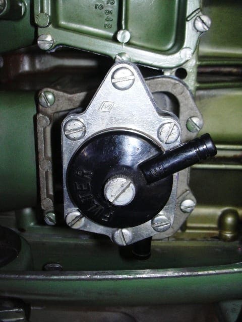
-
This reply was modified 7 years, 6 months ago by outboardnut.
-
This reply was modified 7 years, 6 months ago by outboardnut.
January 26, 2019 at 2:47 pm #164873Now you’re talking, that’s the way to do it.
January 26, 2019 at 3:51 pm #164876(passes air both directions after the conversion).
Duhhhhh, what was I thinking? Sometimes I’m not too brilliant until the second cup of Joe has had time to settle in.
-
This topic was modified 7 years, 6 months ago by
-
AuthorPosts
- You must be logged in to reply to this topic.