Home › Forum › Ask A Member › Flow-Chart for OMC Carburetors??
- This topic has 7 replies, 6 voices, and was last updated 6 years, 3 months ago by
 Mumbles.
-
AuthorPosts
-
January 17, 2018 at 4:06 pm #9027
Hello…..
Have any of you seen a flow-chart similar to the one I have in the picture for the typical OMC carburetors used on the 12-15-18HP motors sold through the 50’s and 60’s?
Something like this:
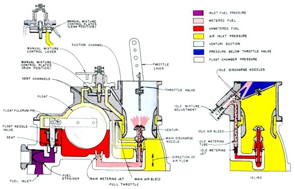
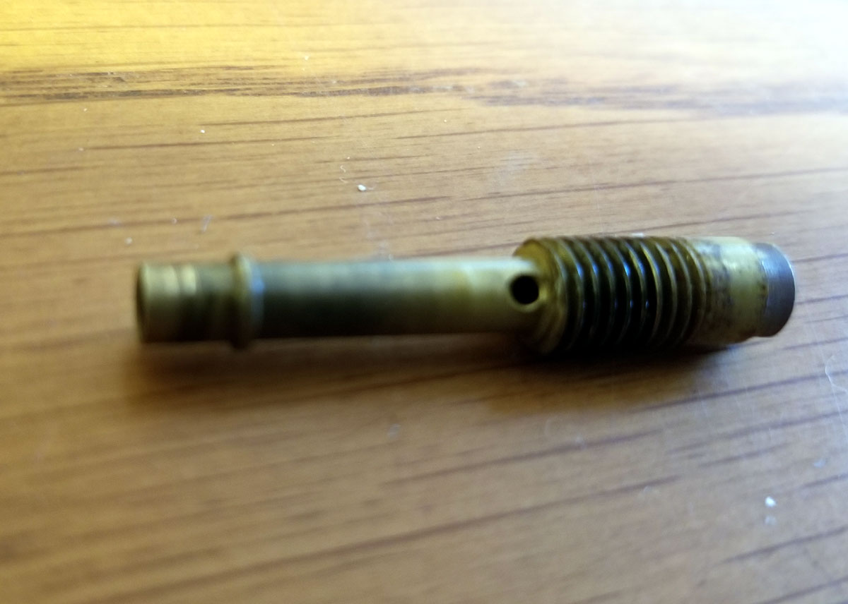
In particular…..when fuel exits the two holes in the main nozzle shown below……what passage does it go through and where does it exit?
 January 17, 2018 at 5:58 pm #69821
As I understand it:
Four stroke (car) carburetors have an accelerator pump to shoot an extra gob of gas into the manifold when you suddenly floorboard it. Instead of that, outboard carbs have that "pocket" that fills with gas while at slow speeds. When you suddenly bury the throttle, gas is sucked out of that pocket to temporarily enrichen the mix, then after that, it is metered by the high speed needle.
Oversimplification, I guess, but that’s all I know. Can’t even guarantee that.
January 17, 2018 at 9:04 pm #69824Those 2 holes are an air intake to emulsify or bubble the fuel before exiting the carb..as in main air bleed. Helps with vaporization. The small end is where the fuel exits into the venturi. Put a hole in your soda straw above the soda and suck. Thats what the 2 holes do.
When at low speeds the float level is higher than at full flow. So at idle the level in the bowl is high. Crack the throttle and the fuel level starts out high but soon gets drawn down to steady state. Tapered float needle is why that happens. That gives some accelerator enrichment without a real accelerator pump.
Looks as though that carb varies the float bowl vent pressure to control hi speed mix..
January 17, 2018 at 11:32 pm #69830Reminds me of an aircraft carbinator, no pump. 😉
January 18, 2018 at 2:53 am #69841
Frank is right on . . . 😎
 January 18, 2018 at 3:17 am #69844
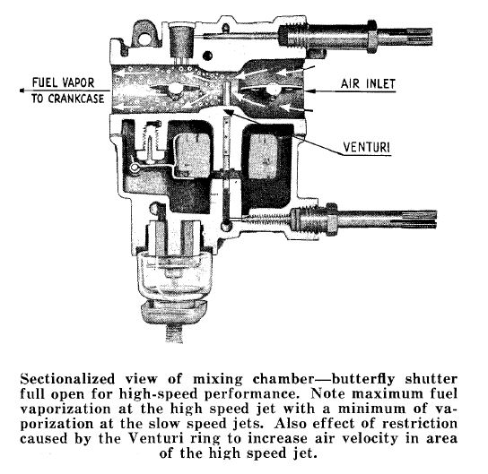
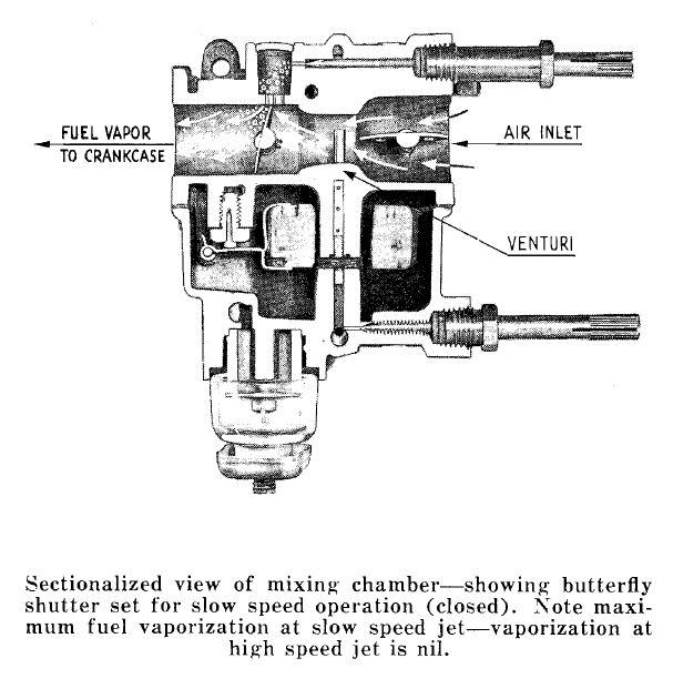
This is all I could find in the service manuals.
Attachments:
 January 18, 2018 at 12:22 pm #69848quote Garry in Tampa:
Frank is right on . . .Actually, I think both theories are correct. I just didn’t take it far enough. When you bury the throttle at slow RPM, the air velocity through the venturi is low and extra fuel must be admitted via an accelerator pump or otherwise, and once the RPM increases the air velocity increases. Then the holes add air to help emulsifiy and vaporize the fuel and correct the mixture ratio. At least that is how I remember it.
January 18, 2018 at 3:15 pm #69858Don’t forget, that while idling, only one of the metered holes in the fuel well is allowing fuel into the motor but as the throttle is opened up, the other holes are exposed to the low pressure air flow allowing more fuel in until finally, the throttle is open enough to allow a large enough volume of air to pass thru the venturi to create enough of a vacuum to draw fuel up through the high speed nozzle. The small bleeder holes in the nozzle allow air into this fuel flow to make it come out in more of a mist instead of in large droplets as it would without the bleeders. This process, when working properly, is what gives a smooth transition between low and high speed operation.
-
AuthorPosts
- You must be logged in to reply to this topic.