Home › Forum › Ask A Member › RDE-18 powerhead to exhaust plate/gaskets
- This topic has 62 replies, 13 voices, and was last updated 5 years, 10 months ago by
 outboardnut.
-
AuthorPosts
-
February 6, 2017 at 1:19 am #52484quote Richard A. White:So should we be drilling those holes or leaving it be?
Well it was the last known advice from OMC on the matter. Use the lower crank bearing that accepts carbon seal, use carbon seal, remove baffle plate, use flat plate with no sound restriction tubes, and drill out the 1/4" holes. As well as greasing splines of course. I do not believe there was a service bulletin after that on the matter that Im aware of.
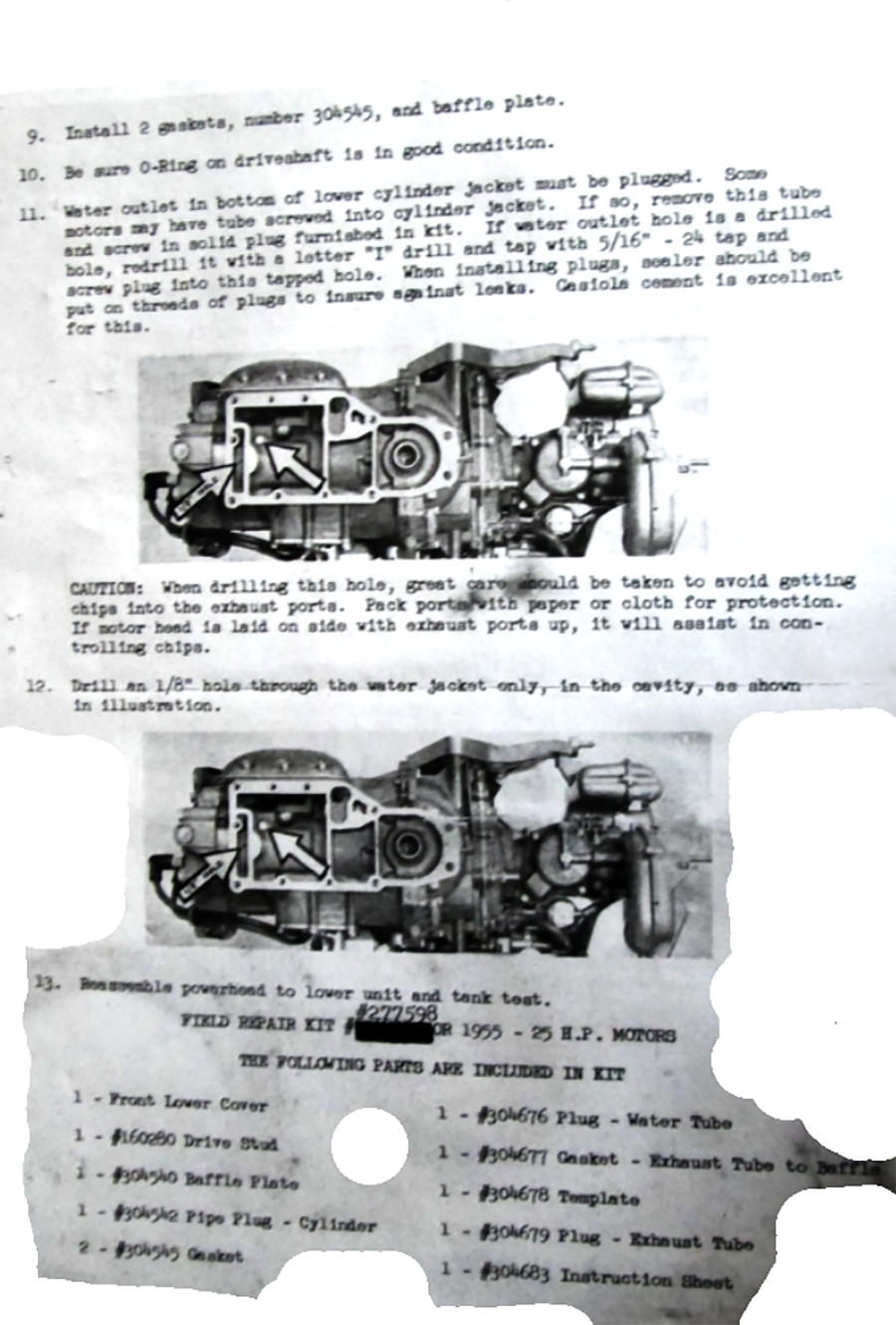
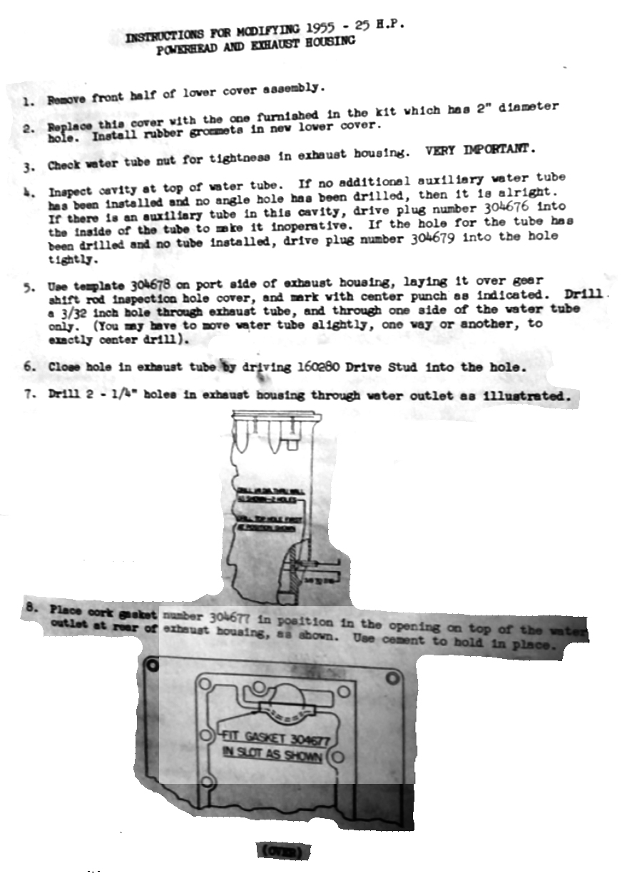
February 6, 2017 at 5:46 pm #52526For 1955 RD17 only -Here is Field Repair Kit p/n #277598 with instruction sheet #304683 info from Ed Sam (Thank you Ed). Took a quick look and it ADDS the baffle into the 1955 motors which was removed by th later mod. It also makes some changes on the bottom of the powerhead and the top of the exhaust leg. If I were working on an RD17 I would look this over and compare to the photos of the RD18 above before making the later mod changes as summarized by Chris_P above. As things are now we do not have the final written OMC mod/bulletin for the 1955/1956 RD17/18 motors.


 February 6, 2017 at 9:30 pm #52536
OK this is a great thread! I am currently in the middle of a RDE-17 myself so now you guys have me wondering. Should I take the baffle plate out? I looked at mine and it in fact has been modified partially meaning that the 1/4" hole in the lower front pan has been expanded to 2" but the exhaust is untouched. Should I be looking for a solid plate and drill the holes or will it matter? Just wondering what the best solution is if I want it to be a runner. Here is an indirect picture of the enlarged hole on mine and one of the exhaust leg.

 February 6, 2017 at 9:40 pm #52538
The 2" hole is fine. I would take the baffle plate out. Does the exhaust have the two 1/4" holes drilled? you need to look at the bottom of the powerhead and the top of the exhaust leg Do you have photos?
February 6, 2017 at 9:53 pm #52540No holes drilled. The plate installed has the two small restriction tubes. I think the only thing that was modified was the front pan. If this would have came up a week or two ago I would have been able to get some pictures but as it is right not it is back together. I will be disassembling again to repaint though so I can do whatever mods I need to then. I did have the crappy lip style lower seal but changed that to the carbon type.
February 6, 2017 at 10:30 pm #52545I missed your photo of the top of the exhaust. Looks like the exhaust was not modified. I would trace the tube plate and make a solid one or just get a couple of "patches" welded on TOP of the plate. The other thing I would look at is to make sure that the water discharge from the powerhead is thru a small hole in the small compartment at the aft end of the powerhead same as the RD18 is. (see photo above) The kit above talks about other mods for some RD17s that sound like they may not apply but I didn’t have an RD17 to look at. So read it carefully. I think the idea was to make RD17 like initial configuration of RD18 but again, no experience. My guess is you will find you are good to go removing baffle, putting in a small blank plate and drilling but again no experience with RD17. (Like Bill I would just hate to drill but I would do it.)
BTW when I took my Utah motor apart the blank plate was loose and out of position, no sign of screws. Looked like these short screws just loosened from vibration. The tube plate in the RD18 parts motor was similarly loose and out of place. Was your tube plate in place?
On my motor I am going to just replace the blank plate with new screws and use a single gasket between the powerhead and the exhaust with no baffle plate.
I have enjoyed reading about you project, always just loved the green motors and aluminum boats.
February 6, 2017 at 10:35 pm #52546No mine was loose as well. The stainless screws that are in it I bought at the local parts house and locktighted them in to prevent them from rattling loose. I guess it will be easy enough to just make a solid plate out of aluminum to plug that off.
Could you please email me a copy of those service bulletin pictures for some reason they wont open to make them big enough for me to read. My email is hughryan@isu.edu
Thanks for your help
February 7, 2017 at 1:44 am #52557See if this will help. . . 😕


 February 7, 2017 at 2:00 am #52558
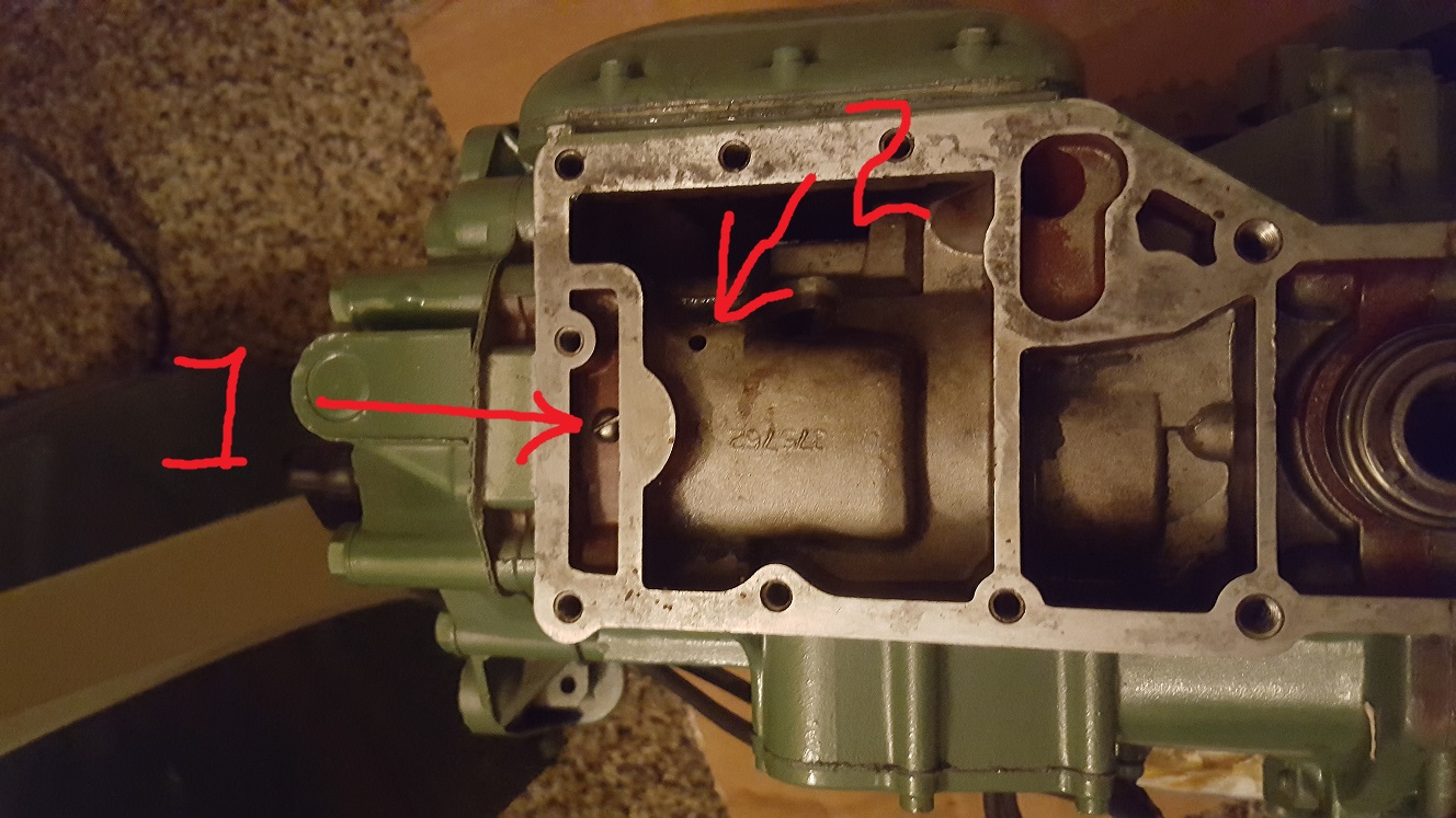
Ok, so Garry’s drawings are awesome but hard to read.., So here are his drawings with numbers 1 & 2 on them that correspond with my motors picture with 1 & 2 marked on the same spots.
Mine looks like it is ok???

http://www.richardsoutboardtools.com
classicomctools@gmail.comFebruary 7, 2017 at 1:38 pm #52579Thank you Garry.
Richard, I think you need a 1/8" hole at position 1 and position 2 needs to be plugged.
I think the object of the kit is to bring configuration of RD17 to that of RD18. See my 1st slide of the Utah RD18. It has the 1/8 hole and there is no opening at position 2. There are two round bosses, one is blank and the other is plugged. Here is a picture of the parts motor RD18. It looks more like yours but again has 1/8 hole at position 1 and position 2 is tight.

Looks like you have a tapped hole at position 1. I hope it is not larger than 1/8 but maybe it could be bushed, plugged or redrilled.
I would not go with this until more experienced members weigh in. Chris_P, others, do you agree?
-
AuthorPosts


- You must be logged in to reply to this topic.