Home › Forum › Ask A Member › Row Boat Motor Magnetos
- This topic has 74 replies, 15 voices, and was last updated 5 years, 6 months ago by
 Buccaneer.
-
AuthorPosts
-
October 24, 2018 at 1:23 pm #84914
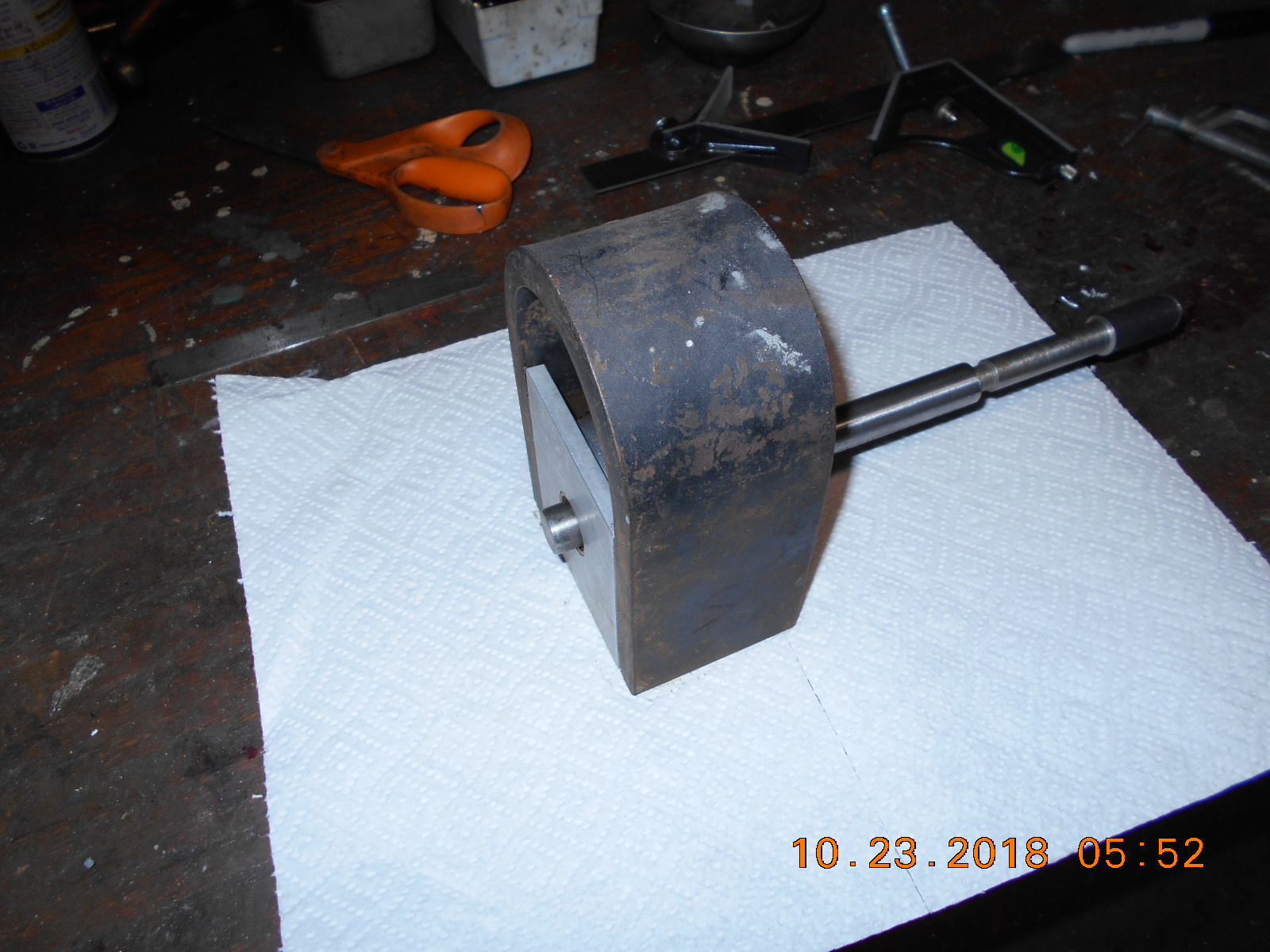
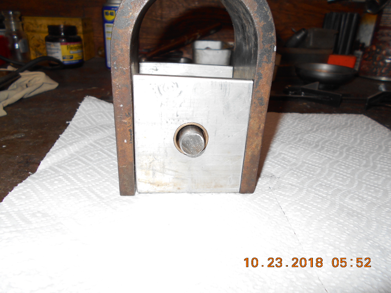
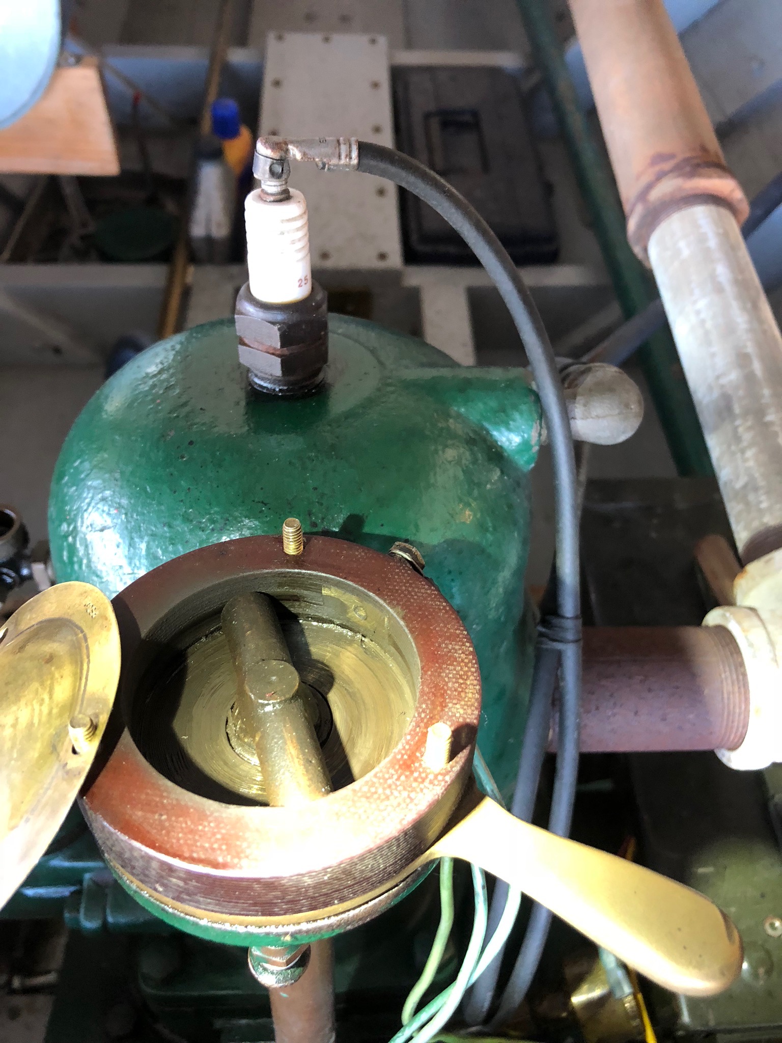
Been building a timer / "mock" magneto as time allows.
The aluminum, round stock bearing cartridge has two
bronze bushings for the rotor / shaft, and a bronze
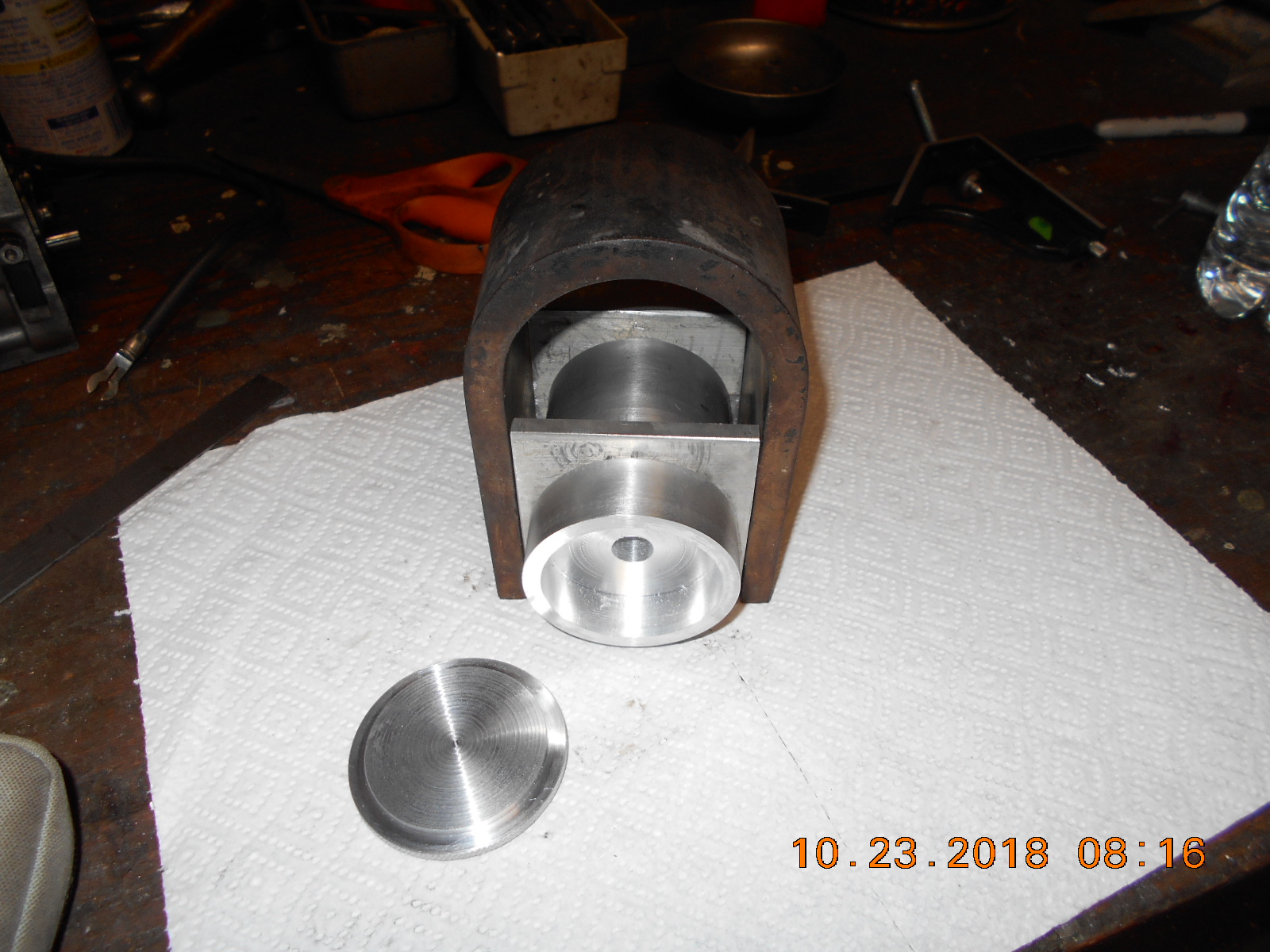
bushing that the stub of the timer housing rides in.I’m looking for ideas how to build "stops" for the timer
so it only rotates a set distance for spark advance,
how much rotation is necessary, and also incorporate
some type of "friction" on the timer so it won’t rotate
around by itself while the motor is running.
Keep in mind, that I have to have room for a set
of points in the timer.Also wondering what type of cam I should grind on the
end of the shaft for my points to operate on.
I was thinking a "D" shape cam would be okay????
The shaft if 5/8", but I’m going to turn it down to
1/2" on the end, to make it work out with the bore
in the timer piece. 1/2" happens to be the size of
the rotor shaft on the Bendix mag I was experimenting with.
I also need to figure out how to hold the rotor shaft
from moving axially.A long way to go, but it’s a start!
Attachments:
Prepare to be boarded!
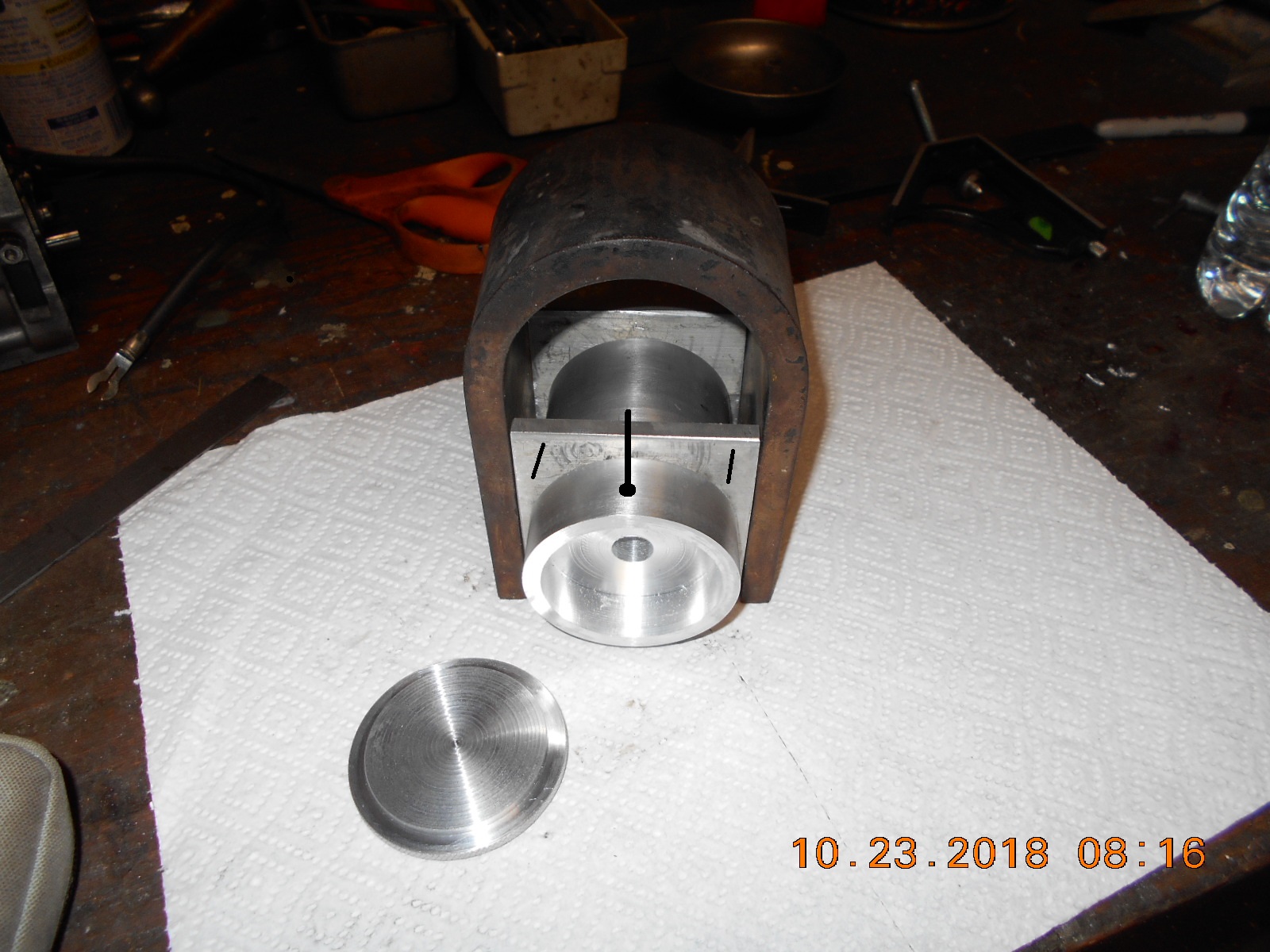
October 24, 2018 at 2:09 pm #84917Well, here’s my two cents… Two pins stick out from the front plate. The whole barrel turns, controlled by a rod sticking up. You can mount points in the cavity, but the model T Ford timer method is a lot simpler: Put an isolated contact through the machined out part of the barrel, and a simple contact spring on the end of the rod. As the spring hits the contact, you make the circuit for a buzz coil.
Based on what I see, you can figure out how to tension the rotation of the barrel.
Wish I had a better drawing program on this computer.
T
Attachments:
 October 24, 2018 at 4:23 pm #84928
Tom, thanks for the idea of the "Stops". That would work quite well.
I looked at a tractor magneto this morning, and there’s less than 90 degrees
rotation (spark advance) on the timer.Regarding the "points less" timer, it sounds like you’re talking about
something similar to what Mr. Parrott showed, in the photo below.
That might be easier than points, but I’d have to figure out some
sort of tensioner for the timer that didn’t interfere.
Thanks!
P.S.- just thought of maybe putting a spring loaded ball bearing
in the mount behind the rotating timer, with detent holes in the
back side of the timer housing to match.
Wonder if that would work?quote Tom Manley:Well, here’s my two cents… Two pins stick out from the front plate. The whole barrel turns, controlled by a rod sticking up. You can mount points in the cavity, but the model T Ford timer method is a lot simpler: Put an isolated contact through the machined out part of the barrel, and a simple contact spring on the end of the rod. As the spring hits the contact, you make the circuit for a buzz coil.Based on what I see, you can figure out how to tension the rotation of the barrel.
Wish I had a better drawing program on this computer.
T
Attachments:
Prepare to be boarded!
October 25, 2018 at 12:59 pm #84954Buccaneer,
Your idea of the spring loaded ball and detents in the timer is similar to the early Lockwood timer. It also used that assembly for ground see the Lockwood side view on page 5 and the bottom of the homemade timer on page 6. The Ferro used exposed stops as Tom stated but Lockwood had them hidden underneath as seen on the Homemade timer. Lockwood mounts were like a half round as seen in the side view which allowed for stop clearance and the stationary stop. Or you could do that by milling slots in your mount. My Ferro RBM and inboard engines only have about 25 degrees of traveI, but are designed to run in only one direction. The Lockwood travel about 150 degrees to allow for reversing. They also have insulators in the bottom of the timer base to break the ground at each end of the travel to shut off the engine. It’s hard to see but look at the end of the detents on the homemade timer, the bigger rounds are insulated. Hope this makes since.
Jim
October 25, 2018 at 1:05 pm #84956Buccaneer,
With your timer being aluminum, I think the points would be easier, the wiper type timer need a insulating ring unless you make it like the Ferro timer.
Jim
October 25, 2018 at 4:23 pm #84968quote JimParrott:Buccaneer,With your timer being aluminum, I think the points would be easier, the wiper type timer need a insulating ring unless you make it like the Ferro timer.
Jim
Jim, I was experimenting this morning with a few sets of different points I had
laying around, and none of them were a good fit. I thought I’d have plenty
of room inside the timer housing, but not so.
Therefore, I was thinking of something similar to the Ferro type in your photos.
I was thinking of using a spring portion of a set of points for the contact.
Thanks.Prepare to be boarded!
October 25, 2018 at 5:23 pm #84971Buccaneer,
That should work fine and is easy to do. The single set of modern points in the Lockwood timer came from Honda but not sure what engine. The ones in the homemade timer were ground down to fit in the timer. Package steel strapping is decent spring steel if you have some laying around.
I like the magneto look you are going for, I’m sure it will turn out fine and will likely run better than a magneto.
Jim
October 26, 2018 at 3:53 pm #85001Jim, I have the spring steel contact made and think it will work.
Next I’m going to attempt to make a detent for keeping the timer
in set positions.
I was wondering what battery you recommend for my buzz coil.
I used to use an old 6v tractor battery for my hit and miss,
but it’s finally deader than a door nail. I know some people
run them off 12 v batteries, but I’d rather not.
Would one of those 7.2 v batteries mentioned for the Merc-o-tronic
testers work okay?
Thanks.quote JimParrott:Buccaneer,That should work fine and is easy to do. The single set of modern points in the Lockwood timer came from Honda but not sure what engine. The ones in the homemade timer were ground down to fit in the timer. Package steel strapping is decent spring steel if you have some laying around.
I like the magneto look you are going for, I’m sure it will turn out fine and will likely run better than a magneto.
Jim
Prepare to be boarded!
October 26, 2018 at 4:53 pm #85004I run my buzz coil on a 7.2 v NiCd, about 1500mA, from a Makita cordless drill. Works just fine.
T
October 26, 2018 at 5:55 pm #85008Buccaneer,
My buzz coils are made with 12 volt components, so I use either 12volt back up lighting batteries, deer feeder batteries, or batteries out of our jet ski’s. In the old days most boats used dry cell batteries. The battery in my plastic ammo can buzz coil previously posted is a back up lighting or deer feeder battery.
Jim
-
AuthorPosts
- You must be logged in to reply to this topic.