Home › Forum › Ask A Member › Testing Solenoids
- This topic has 7 replies, 2 voices, and was last updated 5 years, 10 months ago by
 Buccaneer.
-
AuthorPosts
-
June 30, 2018 at 10:30 pm #10423
How do I verify that I have the correct 12v style starter solenoid
fom the old Johnson? I bought an "aftermarket" solenoid
to rig up a test station / box, and it "said" it was an OMC replacement, but seeing how
when I opened the box it said "China", I’d like to verify.
I know that wrong, automotive type will fry the mercury switch,
(or is that just an issue with the wrong 6v solenoid?)
so I’m assuming that one of the small post is the ground
path to the mercury switch.
The only continuity (as it sits on my work bench) with my VOM on the solenoid is between the two small post.
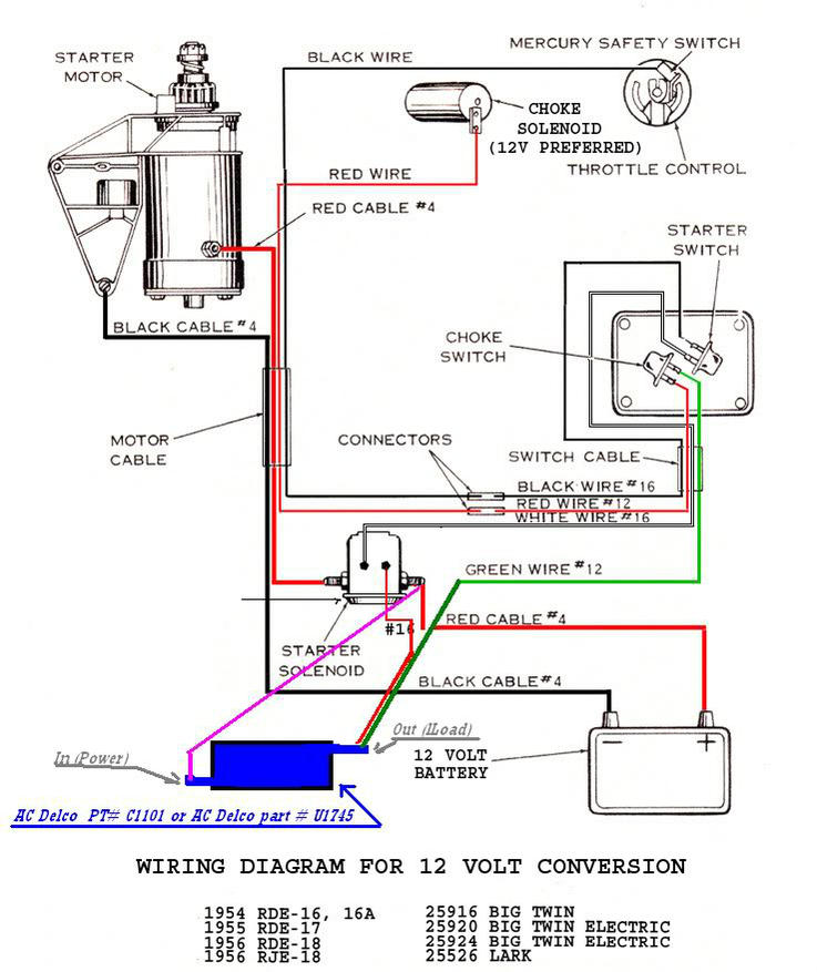
Thanks for any enlightenment!Also, regarding the 12v conversion diagram, why is the wire going to the
small right post on the solenoid, coming off the "down side" of the resistor?
I know that the electric choke solenoid should, buy why the should the
starting circuit come off the down side of the resistor?
Attachments:
Prepare to be boarded!
June 30, 2018 at 10:50 pm #78767Continuity between the two small posts is good. Actually, it will be a few ohms.
There is no connection between the two small posts on a Ford solenoid.
A 6V solenoid is a whole different critter, only one small post.
June 30, 2018 at 11:01 pm #78768quote Buccaneer:How do I verify that I have the correct 12v style starter solenoid
fom the old Johnson? I bought an “aftermarket” solenoid
to rig up a test station / box, and it “said” it was an OMC replacement, but seeing how
when I opened the box it said “China”, I’d like to verify.
I know that wrong, automotive type will fry the mercury switch,
(or is that just an issue with the wrong 6v solenoid?)
so I’m assuming that one of the small post is the ground
path to the mercury switch.
The only continuity (as it sits on my work bench) with my VOM on the solenoid is between the two small post.
Thanks for any enlightenment!Also, regarding the 12v conversion diagram, why is the wire going to the
small right post on the solenoid, coming off the "down side" of the resistor?
I know that the electric choke solenoid should, buy why the should the
starting circuit come off the down side of the resistor?I confess, I drew that diagram, but somebody else added the resistor, and since it is a 12V solenoid, it should not be fed by the resistor. It should be fed by the battery cable side of the solenoid (12V)
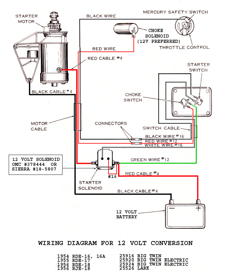
June 30, 2018 at 11:12 pm #78769Here is how I originally drew the diagram–assuming use of a 12V choke solenoid. Insert the resistor in series with the green wire if you want to keep the 6V choke.
 June 30, 2018 at 11:22 pm #78771
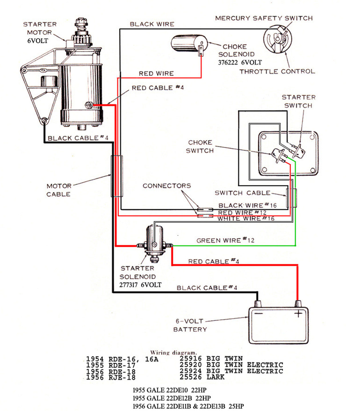
Here is how the factory built them (6V system)
 July 1, 2018 at 12:36 am #78777quote FrankR:Here is how I originally drew the diagram–assuming use of a 12V choke solenoid. Insert the resistor in series with the green wire if you want to keep the 6V choke.
Frank, thanks for the clarification. The way the conversion diagram was, it didn’t make much sense.
I do plan in keeping the 6v choke solenoid, at least for now, as it works fine.
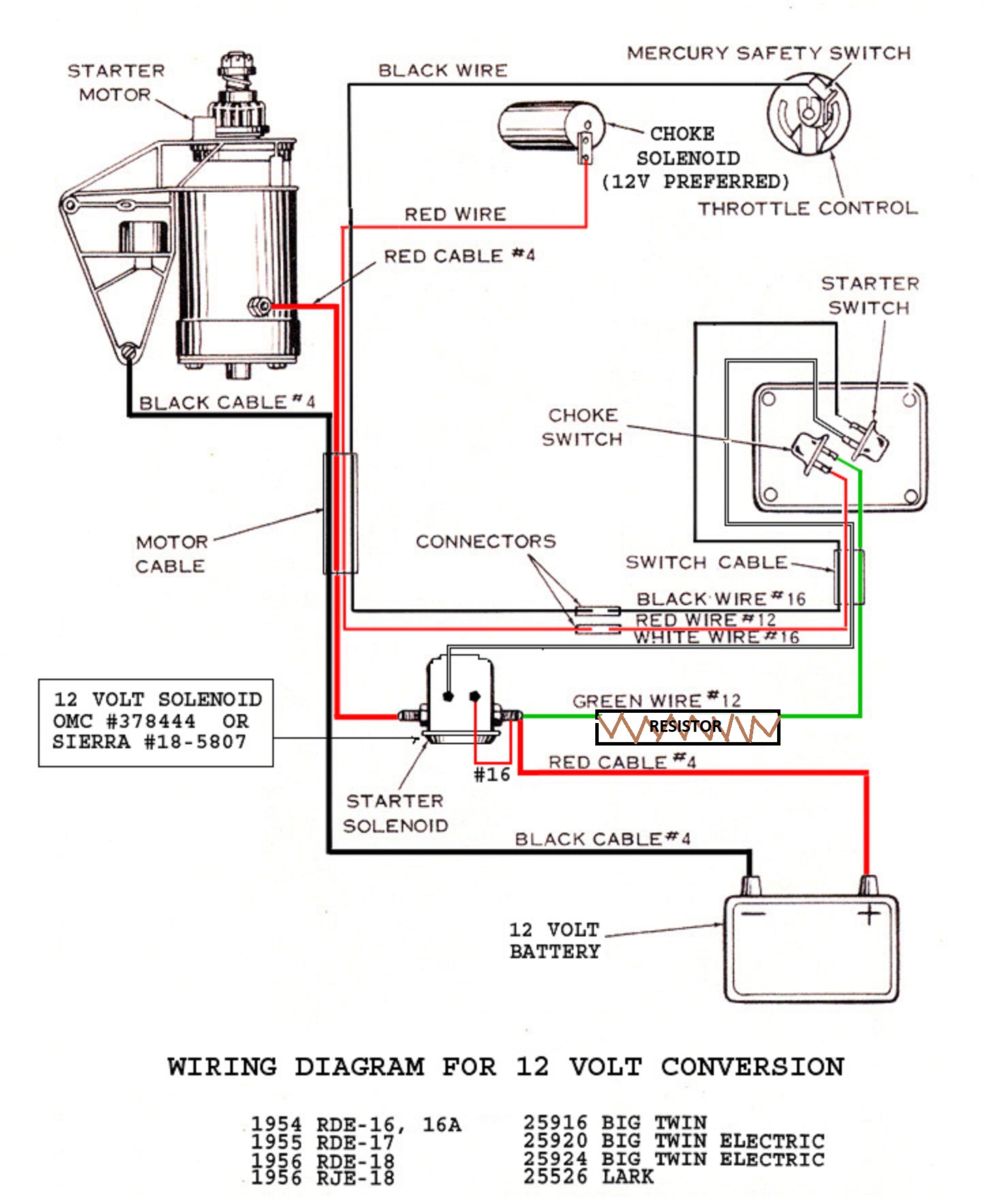
I presume, with the edited diagram, this is the way to way the resistor?
The resistor I bought, is as described below.
Sound okay to you?
——————————————-
"Aftermarket Replacement Electrical Ignition Resistor (0.6 OHM Resistor) made to fit Ford Tractor models:
2N, 8N, 9N with 12 volt conversion (1939-1950).
Used in alternator conversion kits.
Replace Part Number: 8NE10306"
—————————————–I’m still wondering, is it the wrong 6v or wrong 12v solenoid that will fry the mercury switch,
and what’s the internal differences, and how do you tell the difference using a VOM?
Thanks again!
Attachments:
Prepare to be boarded!
July 1, 2018 at 1:30 am #78787Yep, I approve your revised resistor location.
Back to the solenoid. I told up above how to test it with a meter. Perhaps if I explain how they work it will make sense.
The two small studs on an OMC solenoid have an electro magnet pull-in coil between them. When you call for a start, electricity flows in one stud, through the coil and out the other stud to the mercury switch. As it flows through the coil, the voltage is reduced (just as if it were a resistor, which it is—a resistance.) So, the voltage being fed to the mercury switch is considerably less than 12V and the switch can handle it.
Enter the Ford solenoid. One of the two small studs is internally grounded, and electricity flows in one, through the coil, and to ground. The other small post serves an entirely different purpose, which is to feed a full 12V to the ignition coil, bypassing the coil’s resistor. That scheme gives higher voltage to the coil during starting, producing a stronger spark to the plugs.
So—if you use the Ford solenoid in an OMC, the full 12V meant for the ignition coil is fed to the mercury switch, and the switch can’t stand it and burns up.
July 1, 2018 at 2:39 am #78795Frank, you explanation makes good sense. It’s nice to know "why" or
"how" something works instead of just being told "how" to do it!
I’m saving your explanation for my "archives".
Much appreciated!quote FrankR:Perhaps if I explain how they work it will make sense.The two small studs on an OMC solenoid have an electro magnet pull-in coil between them. When you call for a start, electricity flows in one stud, through the coil and out the other stud to the mercury switch. As it flows through the coil, the voltage is reduced (just as if it were a resistor, which it is—a resistance.) So, the voltage being fed to the mercury switch is considerably less than 12V and the switch can handle it.
Enter the Ford solenoid. One of the two small studs is internally grounded, and electricity flows in one, through the coil, and to ground. The other small post serves an entirely different purpose, which is to feed a full 12V to the ignition coil, bypassing the coil’s resistor. That scheme gives higher voltage to the coil during starting, producing a stronger spark to the plugs.
So—if you use the Ford solenoid in an OMC, the full 12V meant for the ignition coil is fed to the mercury switch, and the switch can’t stand it and burns up.
Prepare to be boarded!
-
AuthorPosts
- You must be logged in to reply to this topic.