Home › Forum › Ask A Member › Johnson HS39 carbon rods and springs
- This topic has 24 replies, 5 voices, and was last updated 3 years ago by
 Buccaneer.
-
AuthorPosts
-
December 12, 2020 at 8:39 pm #225080
Anyone have a information on those small carbon rods and springs in the flywheel?
December 13, 2020 at 12:15 am #225088What kind of information are you looking for?
The mag in my Johnson HS-10 just about put me over the edge a few years ago trying to get it to work right. I think Buccaneer has had some experience with these mags to.
Here’s a previous post about these mags.
December 13, 2020 at 9:32 am #225097If I remember correctly, this coil with the carbon brush setup was to make the alternate firing
twin run with a single, double secondary output coil, by grounding out the cylinder that’s
not suppose to fire, via one of the carbon brushes, and a ground circuit in the flywheel.There’s a bakelite piece riveted on the inside of the flywheel with a little “contact spring” that’s
suppose to be the coil grounding path.What I ended up with was the most irratic running motor I ever worked on.
It’s a magneto problem for sure, and in retrospect, thinking about it now,
I bet that the one cylinder is partially “sparking” the plug when it’s not suppose to.I have a video of it running, but I’m not finding it on YouTube right now.
If there’s interest, I can try to post it there.
Perhaps this would be a good motor to re-visit, but thanks for reminding me of my defeat, lol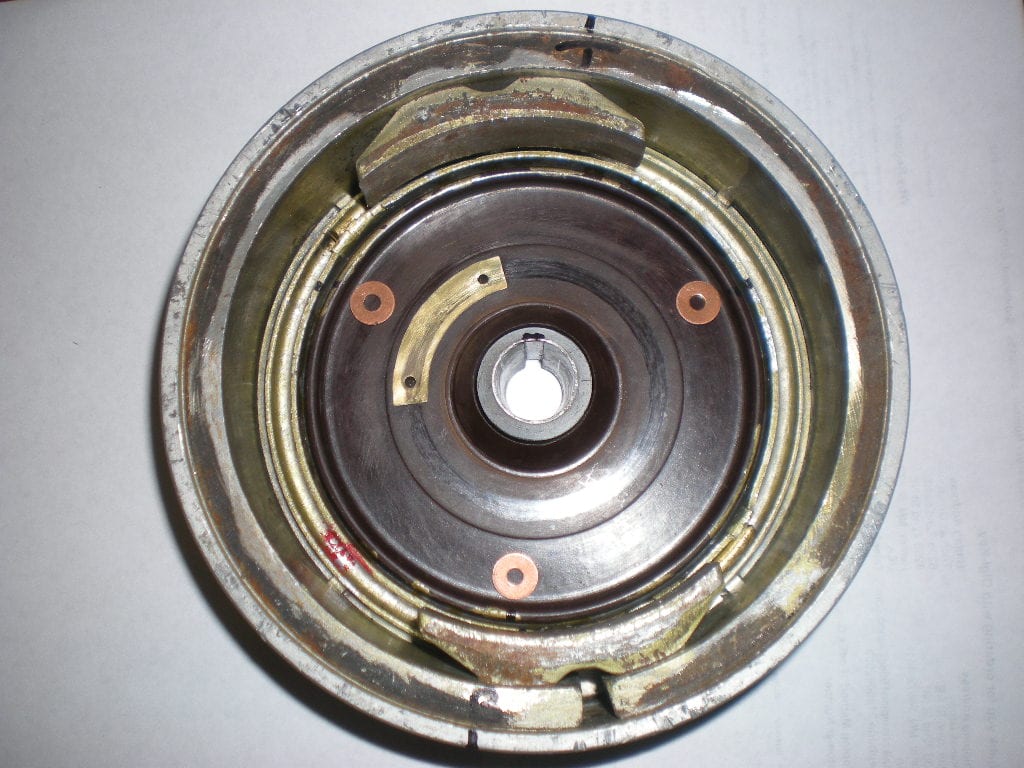
Prepare to be boarded!
-
This reply was modified 3 years, 4 months ago by
 Mumbles.
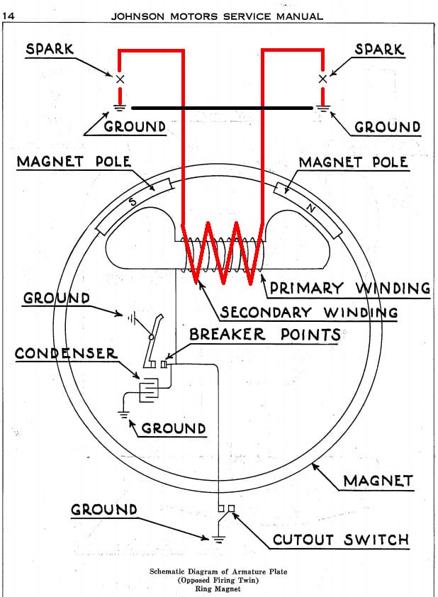
December 13, 2020 at 11:12 am #225100Those things gave me a fit back in “The Day” because I really didn’t understand them. But with what I know now, they aren’t all that complicated. It helps to first understand how it works as applied to horizontally opposed twins (picture below). When voltage in the secondary winding is high enough, the electrictal flow is as follows. It flows from one end of the coil, to a spark plug, jumps the gap to ground, THROUGH THE GROUND back to other spark plug, jumps the gap, and returns to the other end of the coil, completing the circuit. Thus, both plugs fire at the same time.
With alternate firing twins, one end of the coil secondary is grounded by the carbon brush, Now the flow is from the ungrounded end of the coil, to the other spark plug, jumps the gap to ground, and back to the end of the coil that is grounded by the brush, completing the circuit. When it is time for the other cylinder to fire, everything is reversed and the other plug fires.
 December 13, 2020 at 12:47 pm #225107
Nice explanation and graphic Frank.
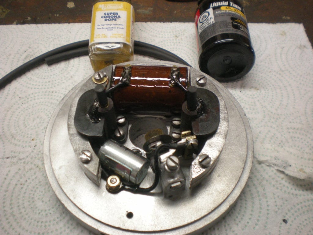
Back when I was trying to figure out the very erratic running HD-15
with this “whacky” ignition, I did some testing and made a diagram
trying to make sense of if things were working correctly as far
as the coil grounding system.Thinking back, all I know is I was using an ohm meter checking continuity
as I slowly spun the flywheel. I have no recollection of if the points,
and condenser were hooked up or not, but I remember getting readings
on the meter that made no sense.
Perhaps one day I’ll try again, but maybe with a different flywheel if I
have one, or can find one.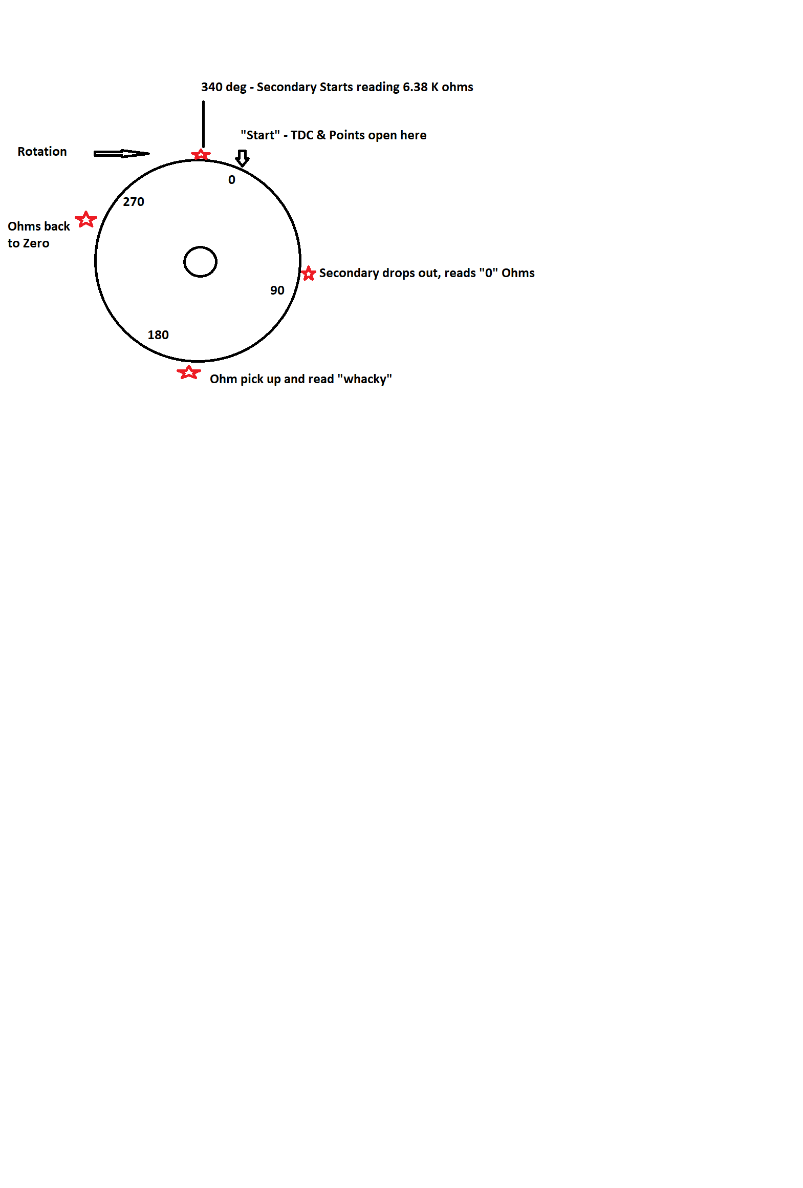
Prepare to be boarded!
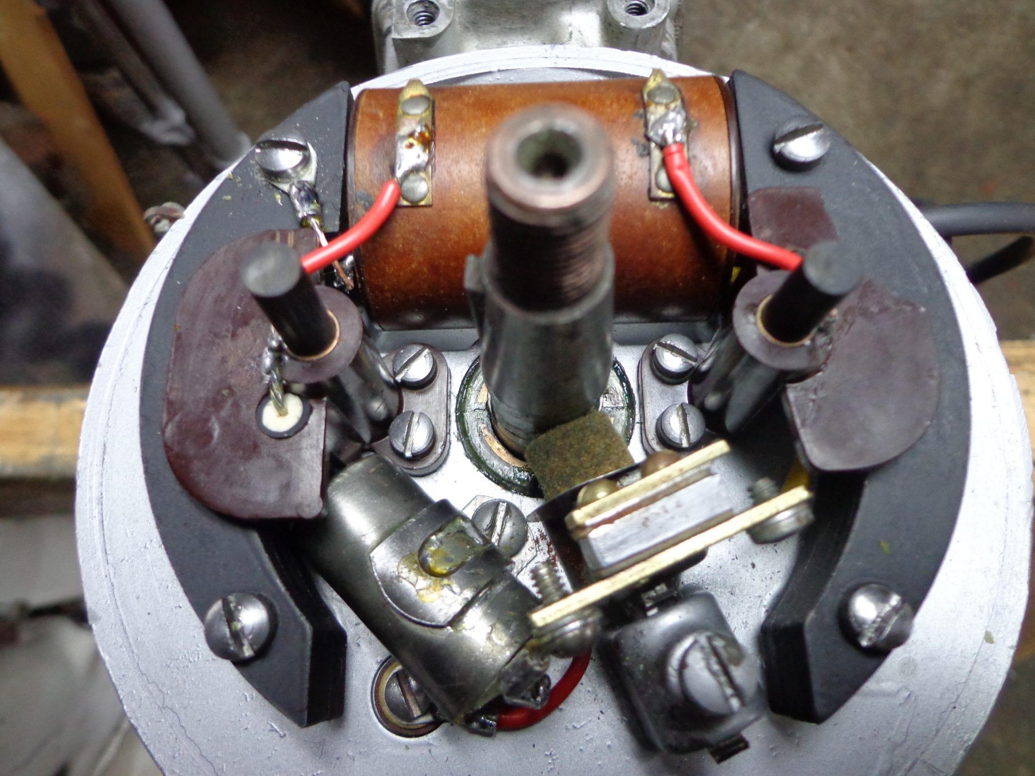
December 13, 2020 at 12:58 pm #225114Just to elaborate a bit on these alternate firing twin mags, the crank has two cams ground on it with one set of points. When the points open, the current goes from one terminal of the coil to one of the carbon brushes, which is temporarily insulated from the flywheel ground by the Bakelite plate inside it, but connected to one of the spark plug leads. Then it travels to the spark plug, back to ground and returns to the second terminal on the coil via the brass plate which is temporarily in contact with the second carbon brush. This completes the circuit. The brass plate is electrically bonded to the flywheel by a small spring under the plate. As the crankshaft turns 180 degrees, the process repeats itself to fire the other spark plug, but now the opposite carbon brush is insulated from ground, firing the second cylinder.
December 13, 2020 at 2:46 pm #225123Buccaneer, if you did have the points & condenser hooked up, that would explain your wacky Ohms reading. The voltage generated by the magnets passing the coil was being applied to the Ohm meter. As you probably know, resistance readings cannot be done with power applied.
December 13, 2020 at 4:18 pm #225132I had an inkling that the carbon conducted electricity and could only do so when in contact with the brass plate. What I am trying to determine is the length of the rods and how many of them. I have two springs and two rods but they are different lengths.
Is the single set of points adjustable and is it gapped to 0.020”?
Is there any adjustment that I have to do to the carbon rods and springs before I put the flywheel back on?
December 13, 2020 at 4:21 pm #225133Thanks Mumbles that makes sense. Do you have dimensions for those carbon rods? Diameter and length?
December 13, 2020 at 4:25 pm #225134That is how my flywheel looks. Just need to make sure I have the right dimensions on those carbon rods. I may have to make new ones
-
This reply was modified 3 years, 4 months ago by
-
AuthorPosts
- You must be logged in to reply to this topic.