Home › Forum › Ask A Member › Johnson HS39 carbon rods and springs
- This topic has 24 replies, 5 voices, and was last updated 5 years, 2 months ago by
 Buccaneer.
-
AuthorPosts
-
December 13, 2020 at 6:05 pm #225143
I’m taking notes for if and when I ever revisit this motor. Thanks for the good info!
Prepare to be boarded!
December 13, 2020 at 6:17 pm #225144I uploaded the video of my HD-15 with this Rube Goldberg ignition system.
Prepare to be boarded!
December 13, 2020 at 6:52 pm #225154Thanks Mumbles that makes sense. Do you have dimensions for those carbon rods? Diameter and length?
I’m afraid I never took note of them but if one of yours is shorter than the other, couldn’t the spring be stretched a bit to compensate for it?
They have to be close to 1/4″ thick as I used a .22 or .223 bore brush to clean the tubes they ride in.
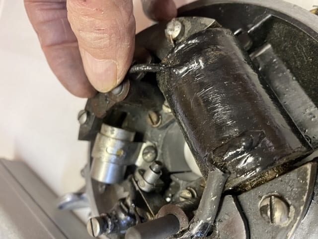
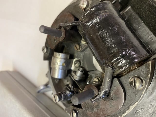
December 14, 2020 at 8:46 am #225195I don’t want to stretch the spring. I noticed in the picture of the ignition plate that the rods appear to be protruding out at least 3/4 to 1″. This means that those rods extend down into the hole some undetermined length. Mine are barely 3/4″ long.
How can I find out if anyone has these rods for sale or knows the original length of the. I can get conductive rods from McMaster Carr, and I think graphite can be machined. But I would at least like to buy the right diameter and then cut them to length and radius the tops.. If those rods are not making good contact I can see where they would cause a problem with the engine firing properly.
Are their experts out there on the HS39 1939 Johnson Sea Horse?
December 14, 2020 at 5:58 pm #225241For what it is worth the rods are 0.250″ conductive graphite. There is a 1/8″ shoulder on one end turned to 0.200″. The top is radiused to allow it to slide between the bakelite and the coper conductor plate inside the flywheel. The springs are 0.4375″ free length, 0.145″ OD, 0.115″ ID. Coils total 7 – 5 active and 2 inactive on the top gripping the shoulder of the rod. The wire thickness is 0.015″. I still do not know the original length, but I am thinking that there can’t be more than a 1/4″ of allowable travel in that spring. One of my rods is 11/16″ and the other is 7/16″. I will try to determine the original length by measuring the free height inside the flywheel when it is mounted. Then I will add length to compress the spring + 1/8″ for the shoulder. This should give me the overall length of the graphite rods. I plan to turn them on the lathe and radius the top that contacts the underside of the flywheel. Since it is graphite it is self-lubricating but over 50 years or so some wear must occur.
I’ve had several suggestions to stretch the springs. I don’t think this is the right approach. It will change the rate on the spring and you could end up with less force against the graphite rod. I think the pressure has to be consistent to make good contact and conduct the pulse from the magneto. There is probably some limit to the wear on those graphite rods, beyond which the electrical connection is not good enough to conduct the pulse to the coil.
I will let you know how the parts turn out and, more importantly, if the engine runs smoothly after I get them replaced. If anyone has any information on the original length of these rods let me know. McMaster Carr has 1/4″ conductive graphite in 6″ and 12″ lengths.
December 14, 2020 at 6:00 pm #225242I doubt that the rods are worn significantly…bett – ch’ that when the flywheel goes on they will be just right. To satisfy yourself, can you indirectly measure where the flywheel commutator surface would lie when the wheel is in place?
Joe B
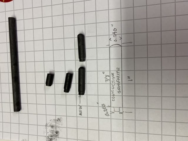
December 16, 2020 at 6:05 pm #225379An update on the graphite brushes. I was able to machine them out of 0.250” conductive graphite rod. Final dimensions are 0.240” OD, 0.200” shoulder and an OAL of 1”. See attached drawings and photos. The springs are internal and attached. You should not need springs
 December 16, 2020 at 6:06 pm #225384
An update on the graphite brushes. I was able to machine them out of 0.250” conductive graphite rod. Final dimensions are 0.240” OD, 0.200” shoulder and an OAL of 1”. See attached drawings and photos. The springs are internal and attached. You should not need springs
December 16, 2020 at 6:17 pm #225387I was able to machine the brushes out of conductive graphite. See photos and drawing. The rod is available from McMaster Carr. But the rod is 0.250” and has to be turned to 0.240”The springs are actually integral to the sockets. I assume they are attached to make sure there is a good electrical connection. See photos and drawing.
December 16, 2020 at 6:23 pm #225391Back in high school shop in the 70’s, one of our projects was to make
a carbon rod “torch”, for lack of a better term.
You’d hook it up to a 12 volt car battery and the carbon would get red hot.
It worked great for unsoldering heavy duty connections like generator fields.
Anyway, the carbon rod we recycled from old “D” flashlight batteries.
If memory serves me correct, they were about 1/4″ diameter, and of course
about as long as the battery.
Not sure if they’d work for the Johnson magneto or not, and I have no
idea what’s inside of a modern battery!Prepare to be boarded!
-
AuthorPosts
- You must be logged in to reply to this topic.