Home › Forum › Ask A Member › How do Atom Computer Ignition modules work?
- This topic has 215 replies, 30 voices, and was last updated 9 years ago by
joesnuffy.
-
AuthorPosts
-
May 14, 2015 at 3:23 am #1486
I got a couple of these Atom computer ignition modules in a motor I junked a while back and got to use them recently.The first motor I put one in (a 1974 2hp Johnson) never has run well and it was out of desperation I tried this part .It starts ,runs and idles like new now .That prompted installing the second in an old Japanese motor that has no spark and no part availability .It has some spark now but not enough to fire so I’m wondering if there is anyway to boost this kind of ignition.Any ideas?
May 14, 2015 at 3:25 am #15908If you can supply manufacturer’s data sheets or manuals for that hardware, it would be helpful for those of us without direct, personal knowledge of the system.
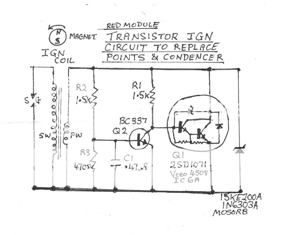
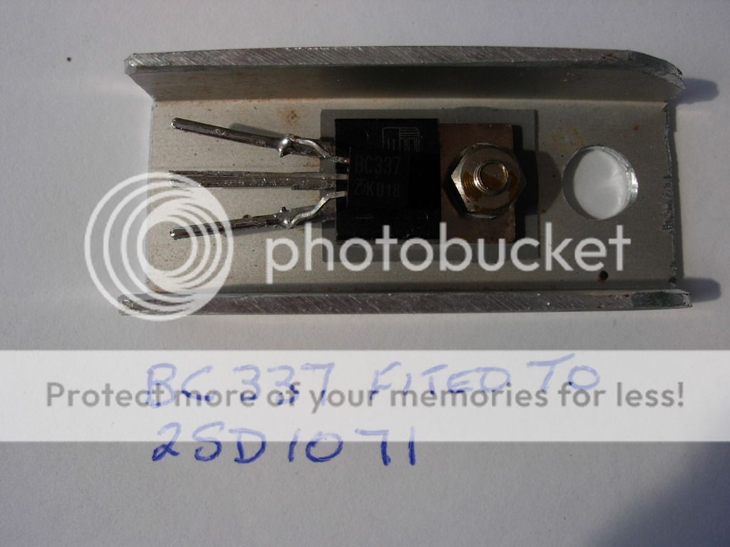
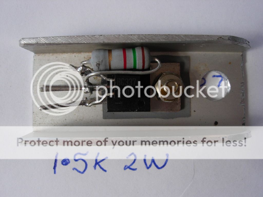
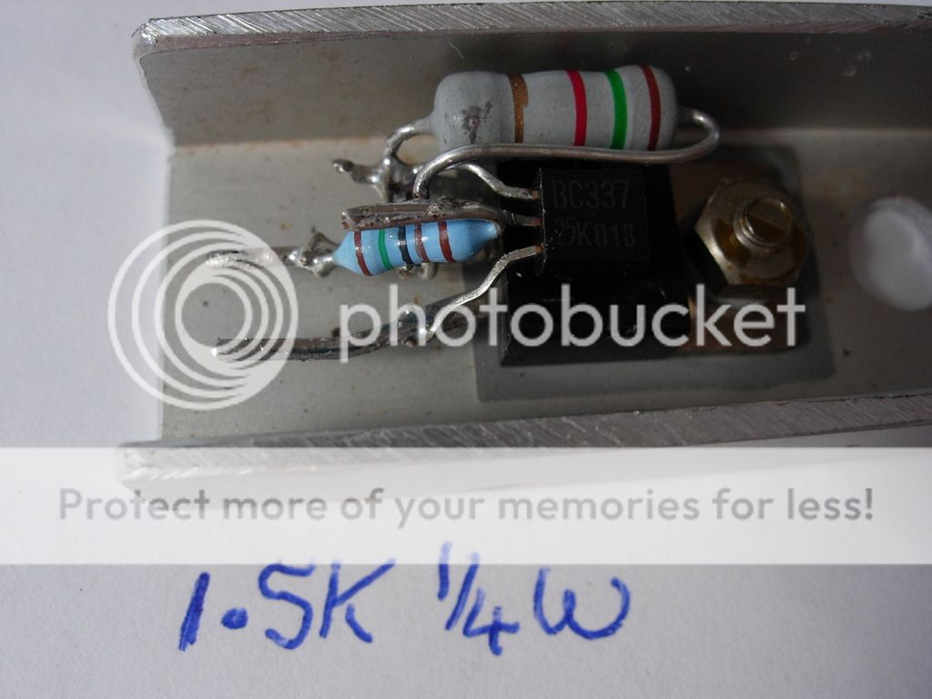
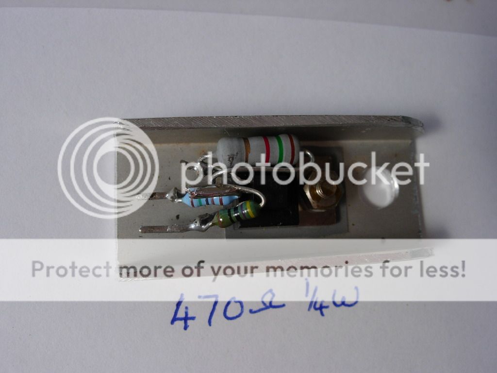
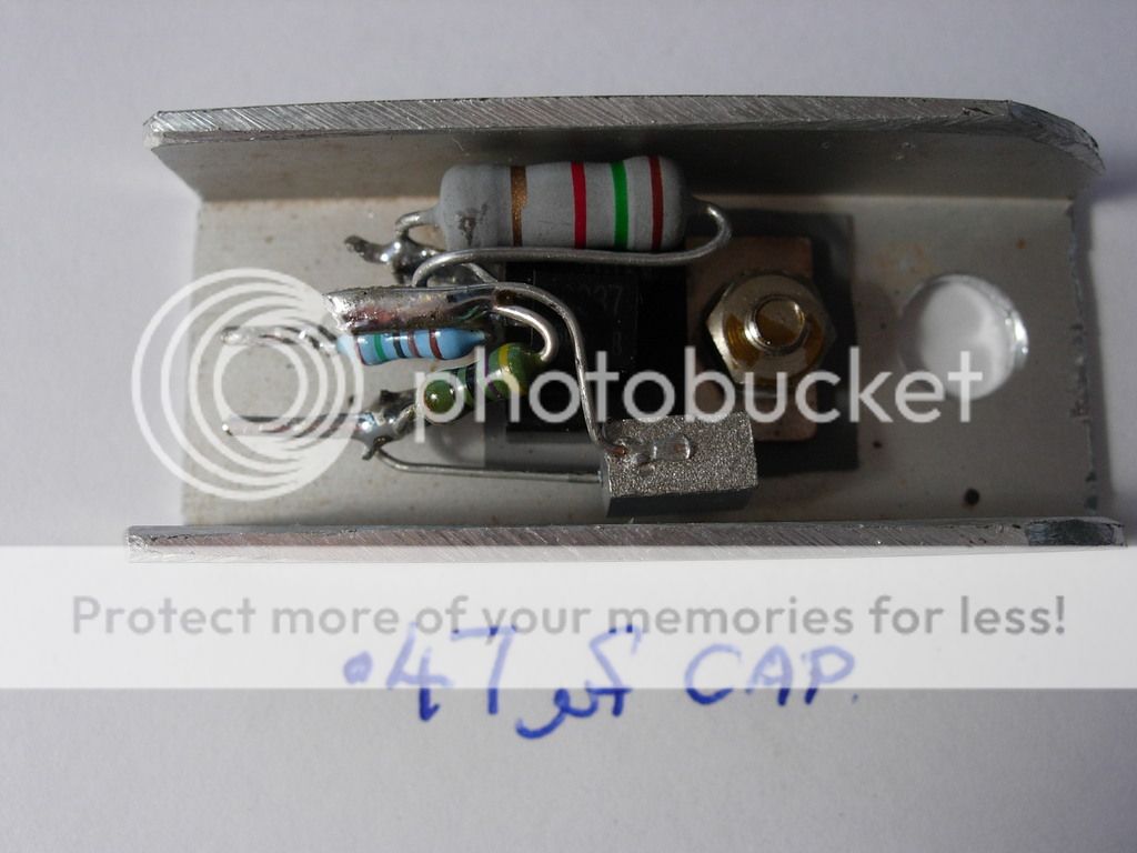
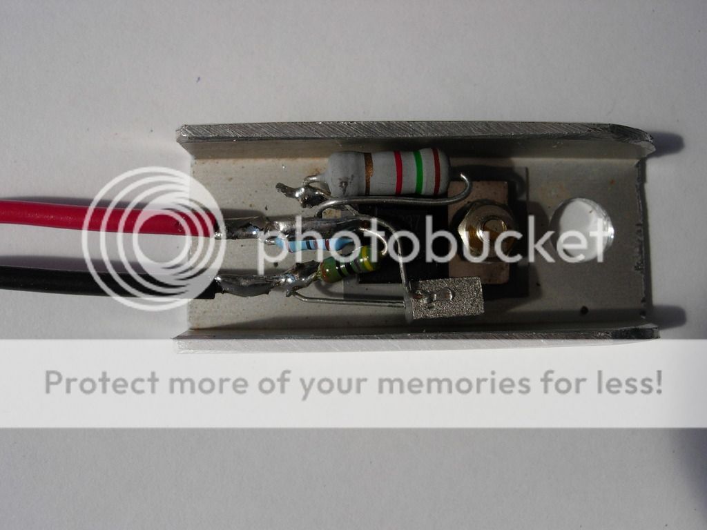
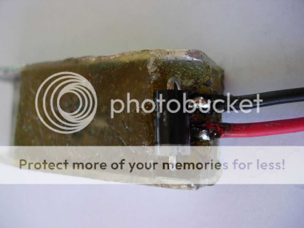
May 14, 2015 at 5:57 am #15921If you want to read up about them Google US Patent 4,163,437 Aug 7 1979. If you want the actual circuit of them with component values to make your own then ive got them, as ive reverse engineered one. There is nothing computer about them at all. Theres 3 resistors, 1 capacitor, 2 transistors in them. On the motor that you have a weak spark try reversing the polarity of the module, also the condencer needs removing as its not required.
May 14, 2015 at 6:44 am #15922quote debe:If you want to read up about them Google US Patent 4,163,437 Aug 7 1979. If you want the actual circuit of them with component values to make your own then ive got them, as ive reverse engineered one. There is nothing computer about them at all. Theres 3 resistors, 1 capacitor, 2 transistors in them. On the motor that you have a weak spark try reversing the polarity of the module, also the condencer needs removing as its not required.I’d be interested in a schematic. Could you post it?
May 14, 2015 at 6:53 am #15923Unfortunatly unable to post on this site. Could email it if you PM me.
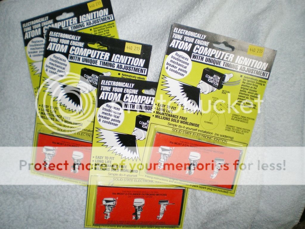
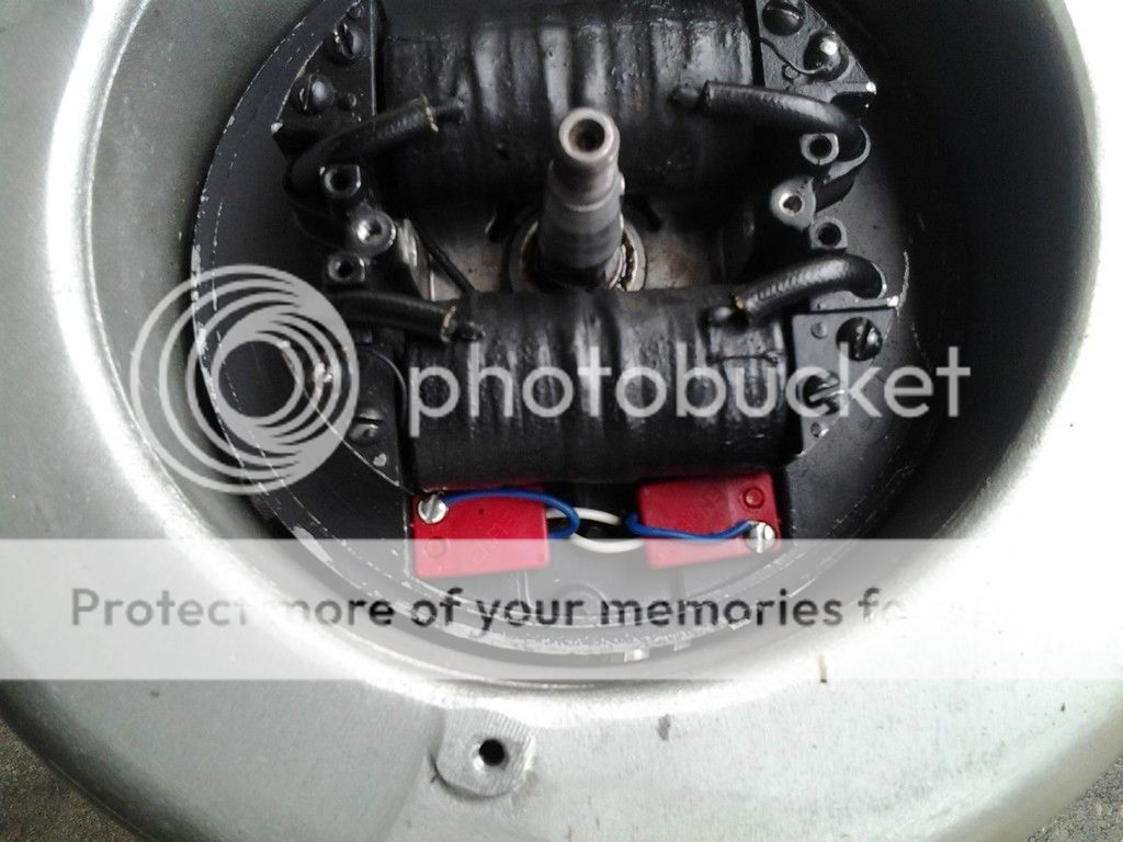
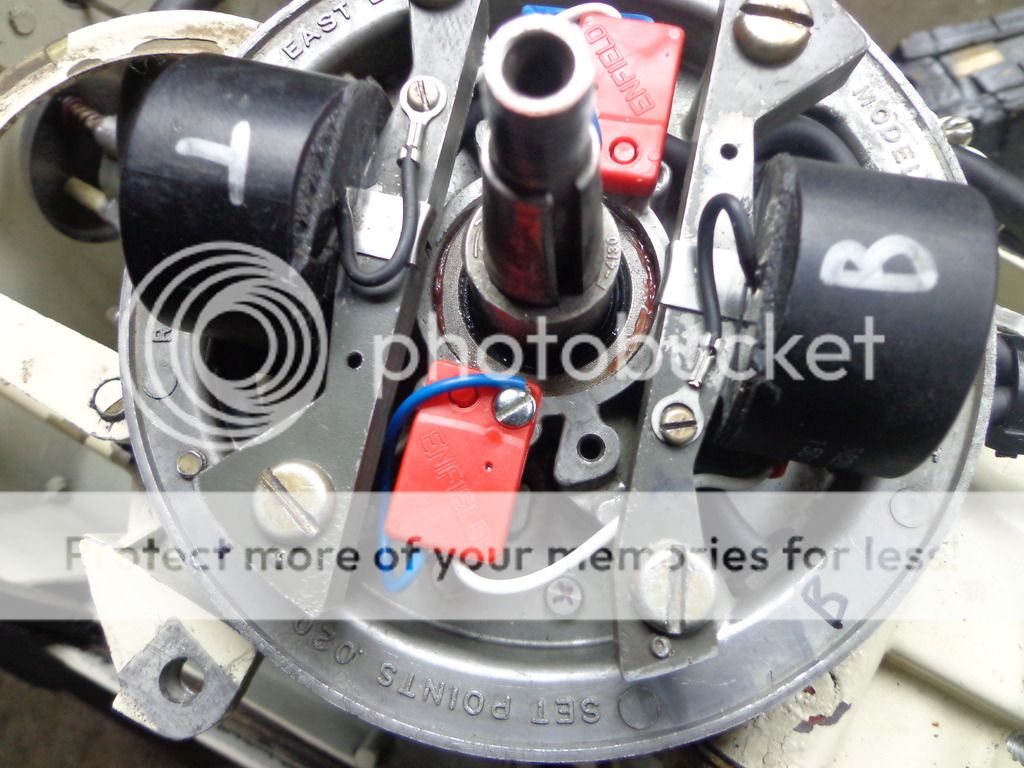
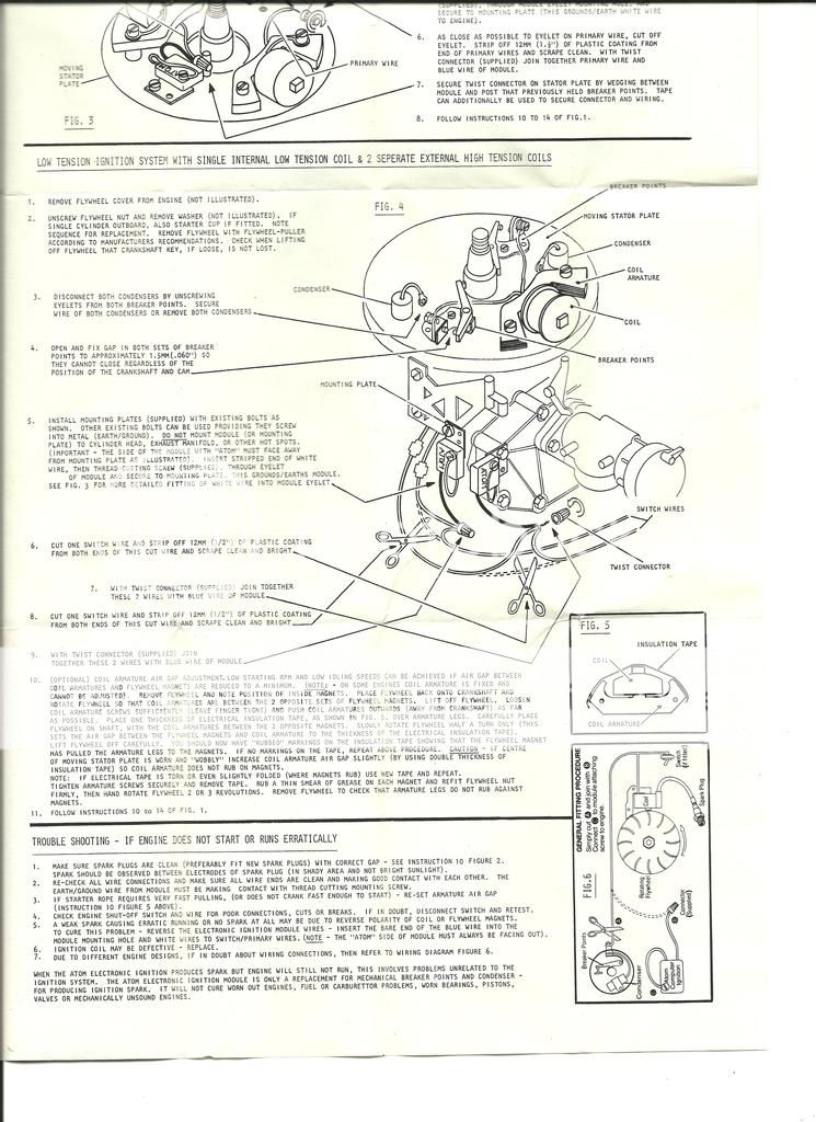
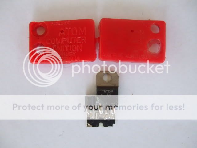
May 14, 2015 at 7:06 am #15925The red modules are for outboards with adjustable timing while the purple ones are for motors with fixed timing. Atom made their modules color coded for different applications in all kinds of magneto equipped motors.
My ’40 Zephyr and ’60 McCulloch both have the red ones in them and it’s like night and day as far as easier starting and smoother idle compared to the points ignition are concerned. If they were still available, I think I’d change all of my motors ignition systems to the Atom modules. I still have four new ones and I think that was the last of them from Banta Saw.
I won’t even talk about the Nova II’s.
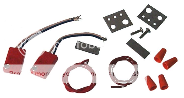
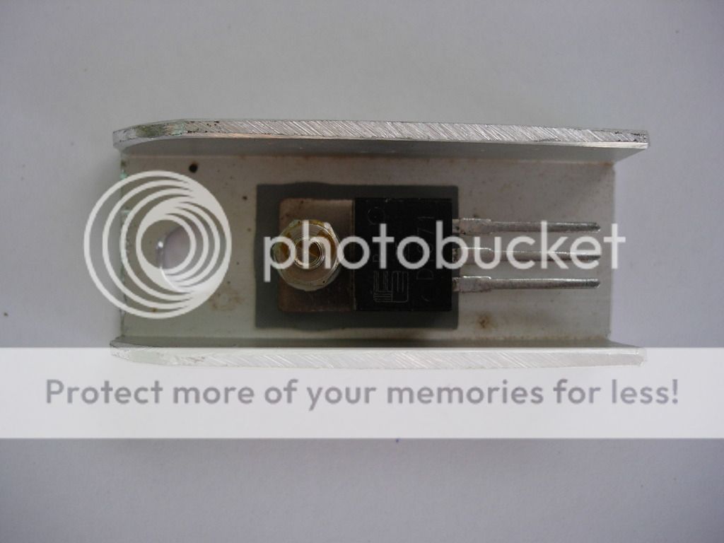
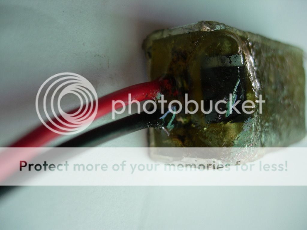
Here’s one Debe took apart.
 May 14, 2015 at 10:57 am #15933
Is there still a source for Atom’s?
May 14, 2015 at 11:23 am #15935You may find some old stock as production ceased in 2005. They used to sell for $28 here in Australia.
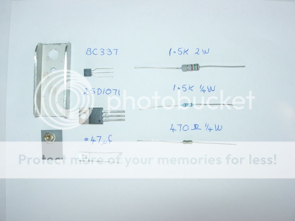
May 14, 2015 at 3:33 pm #15951Here’s Debe’s pictures showing a schematic, materials, and assembly of his module. Mighty fine work!
 May 14, 2015 at 6:34 pm #15955
@Dede / Mumbles
That’s brilliant, thank you both. So let’s take a moment for theory-of-operation..
Correct me if I’m wrong, but this module triggers off of the rising voltage waveform induced across the ignition coil primary? I just can’t see any other way it would work – there aren’t any magnetic sensors and the old points are gone, so they can’t be used as a signal.
How could you possibly establish correct +and+ consistent ignition timing with this? Ep is a function of dB/dT, so the faster the rotor spins, the greater the voltage induced by a particular angle of rotation. If the module is set to always fire at a particular level, this would mean that the timing would advance as the engine speed increases.. and that the base timing angle is affected by things like magnet quality, rotor/stator gap, rotor magnet/coil geometry, and on.
"With Unique Timing Adjustment" is right.. So how the heck does it work? :geek:
-
AuthorPosts
- You must be logged in to reply to this topic.