Home › Forum › Ask A Member › How do Atom Computer Ignition modules work?
- This topic has 215 replies, 30 voices, and was last updated 9 years ago by
joesnuffy.
-
AuthorPosts
-
June 20, 2017 at 2:20 am #59985
Ken L
I joined this list and only recently was granted membership just so I could inquire on wiring details. I can’t seem to post my Picture so I will PM it to you to post.Matt
June 20, 2017 at 3:21 am #59987Joe,
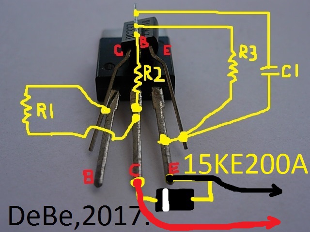
Both the BD649 and the BU931 are NPN Darilington transistors, the only difference is the CE voltage levels. I am going with the 931 because it is rated at 400v max not 100v for the 649. I am afraid that the low voltage level of the 649 will limit the output voltage of the magneto with increase in the magnetic field. Being in the electronic service field I also know how important is is to get the heat out of the device. So you can also place the collector tab of the 649 to ground to remove the heat generated.June 20, 2017 at 3:52 am #59988With electronic modules the condencer value has no bearing on the type of coil as its not directly across the coil winding. But if you go too far of value the module will not work. The original Atom modules were supplied with a small metal heat sink, obviously not shown in a dismantled module. This thread is missing a lot of up dated pictures on the modules as I cant post them here. And im not about to pay to be able to share pictures.
June 20, 2017 at 12:43 pm #59993I will be glad to post any pics you guys like. I thought anyone could post pics? I don’t know if you have to be a member but try doing what I do see below.
I don’t think you can post pics if you use the Quick Reply at bottom of page. Go to top of page and click Post Reply tab then scroll down past where you right you comments in the box and you will see a Attachments Tab click on it and you should be able to post pics.
Hope that helps,
Joehttps://SecreLocal.com - - No Verify - Anonymous Adult Dating -
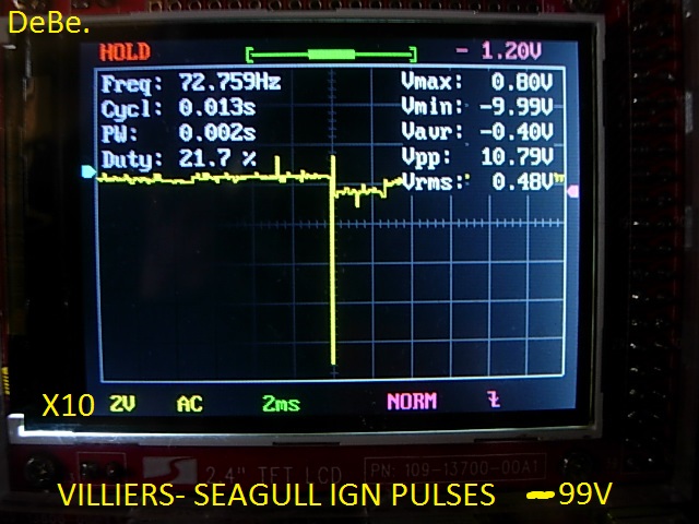
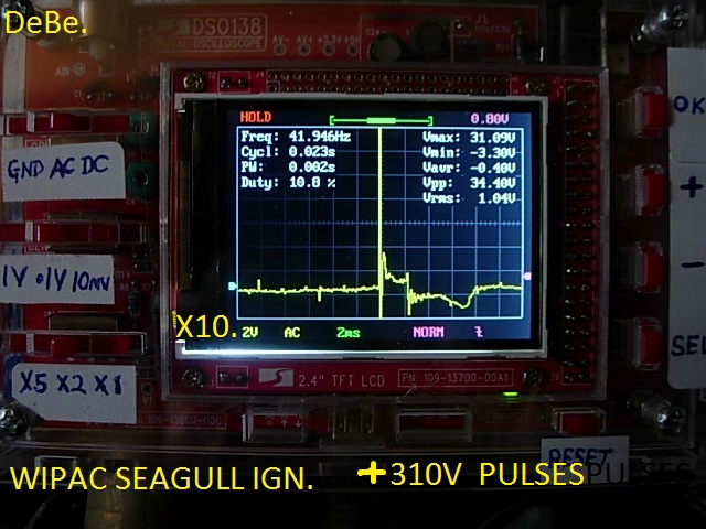
June 20, 2017 at 12:53 pm #59995This is what the wave forms are for 2 types of Seagull outboard ignitions. One is a Wipac magneto & the other is a Villiers magneto. The Wipac is the toughest on the modules due to the high voltage spike compared to the Villiers. Also notice the 2 coils are different polarity. Thanks for that tip on posting pictures, you learn something every day.
 June 20, 2017 at 8:13 pm #60013
Keep in mind these are test modules not sealed with clear silicone or epoxy etc. They are a work in progress.
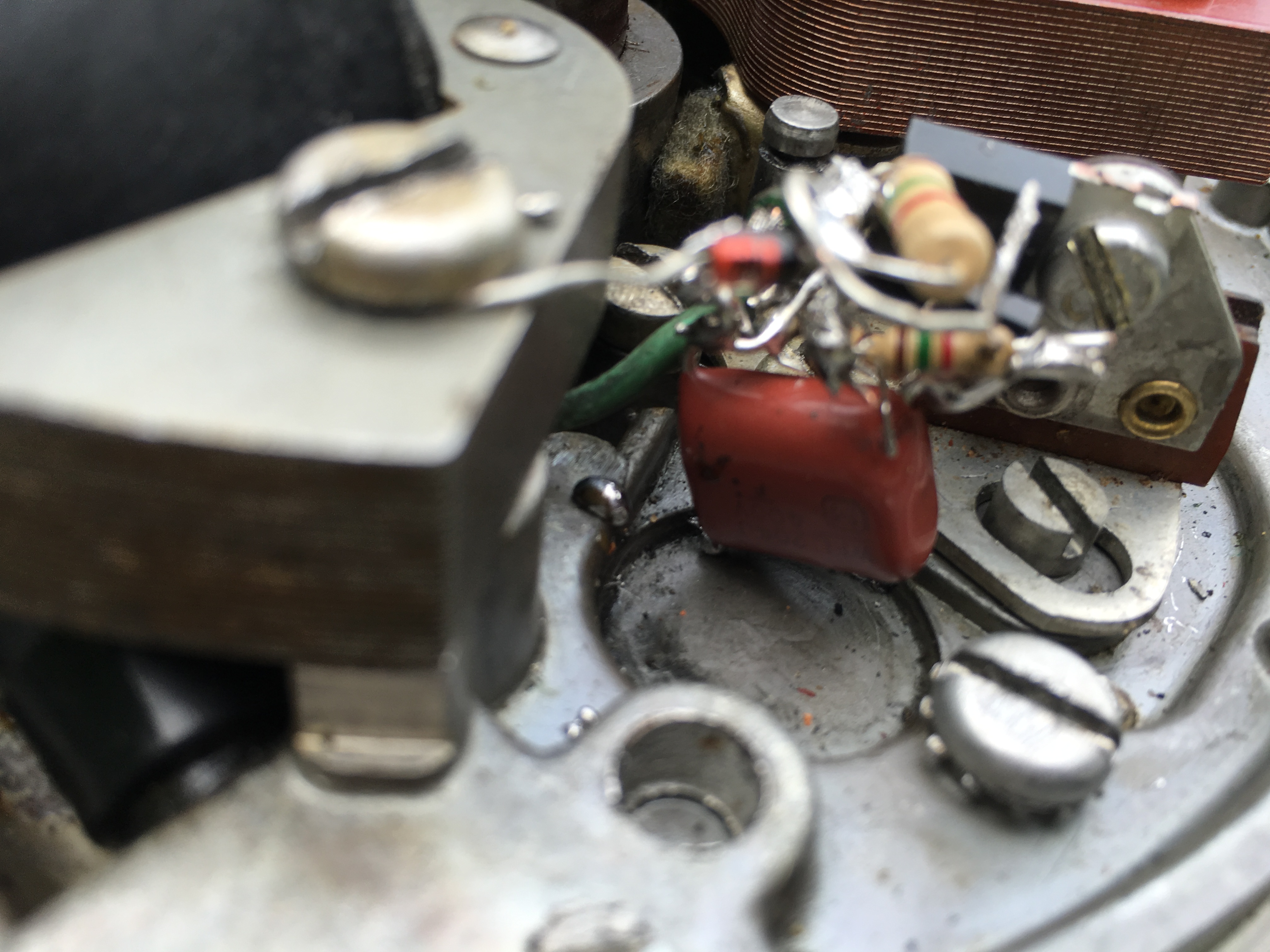
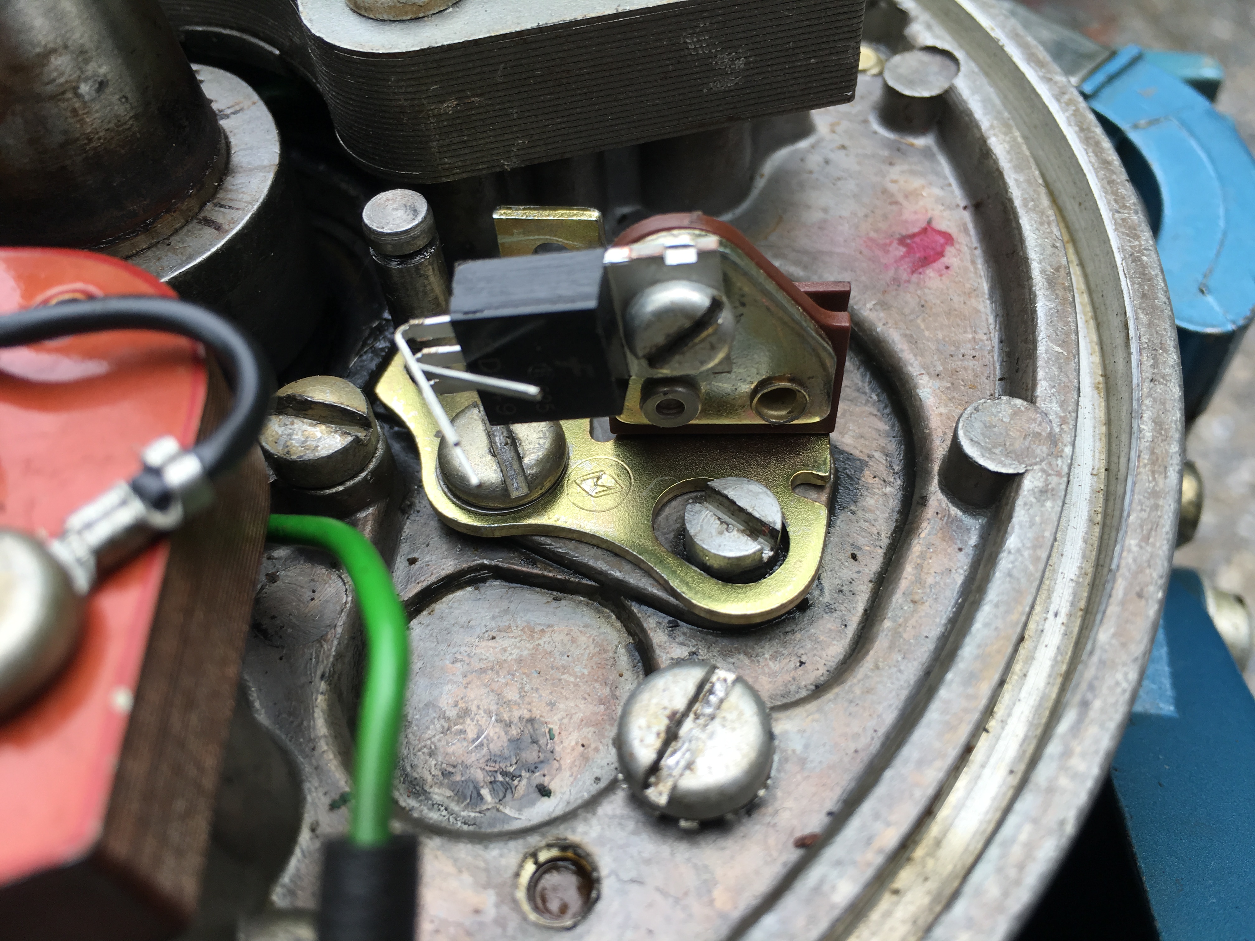
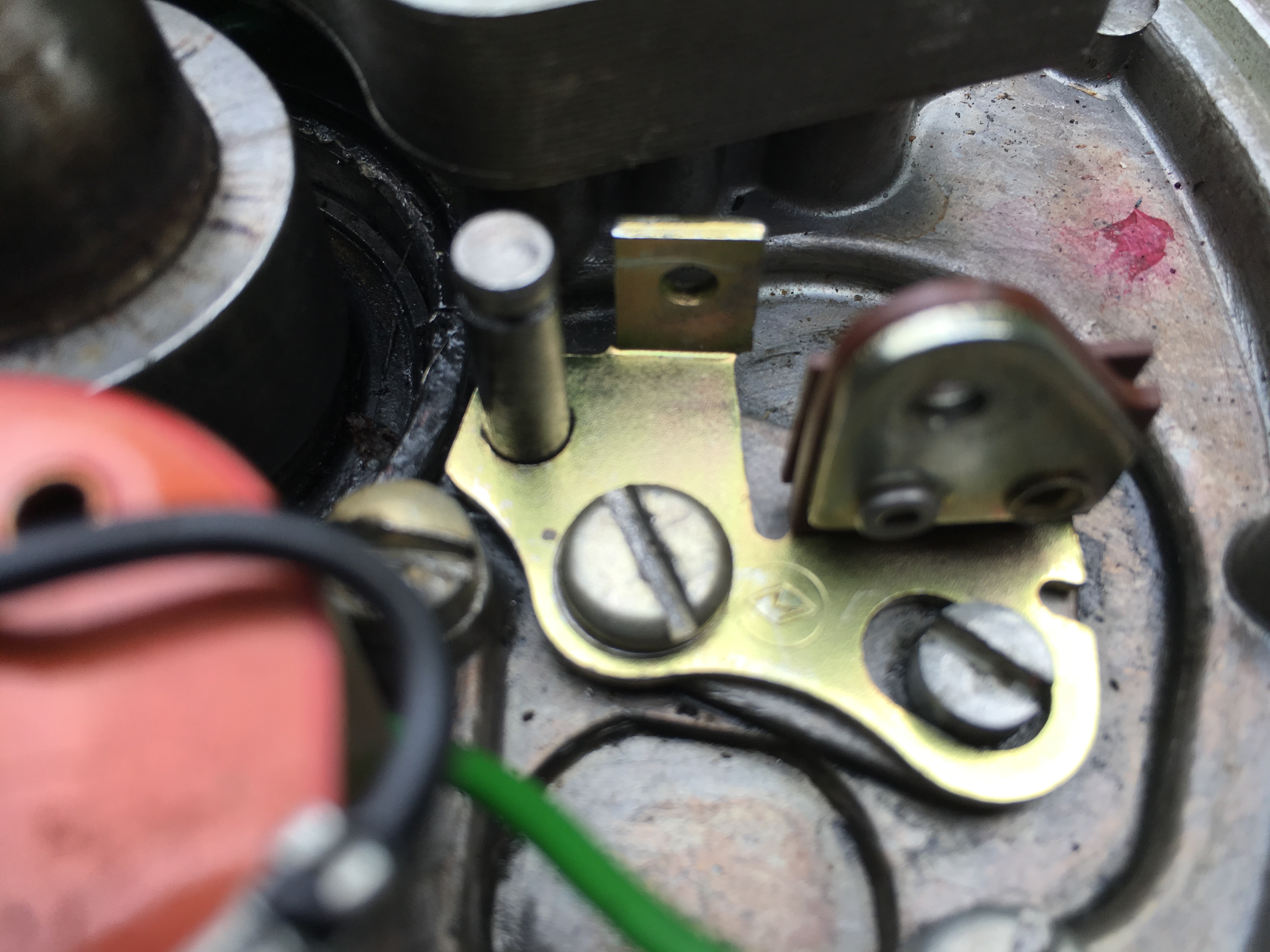
I worked on my 1957 Evinrude 15HP today and made some great strides. I figured out how I am going to mount my transistors for 2 cylinder omc motors 2 stroke of course. Take a look at the pics. Using half a set of evinrude/johnson points is how I am doing it. The half set of OMC points are already insulated against ground and they have metal tapped for screw plate on them for my heat shield. Best part of all is all the original screws can stay in the engine if you desire. If someone wants they can swap it right back to a points system with a new set of points and condensers since all original omc screws are in place. You can see how I mount the transistor to a half set of omc points. I took a pic of only the transistor on the half set of points so you could tell how I am doing it I then took it back off motor and soldered everything to the transistor and then screwed it back on.
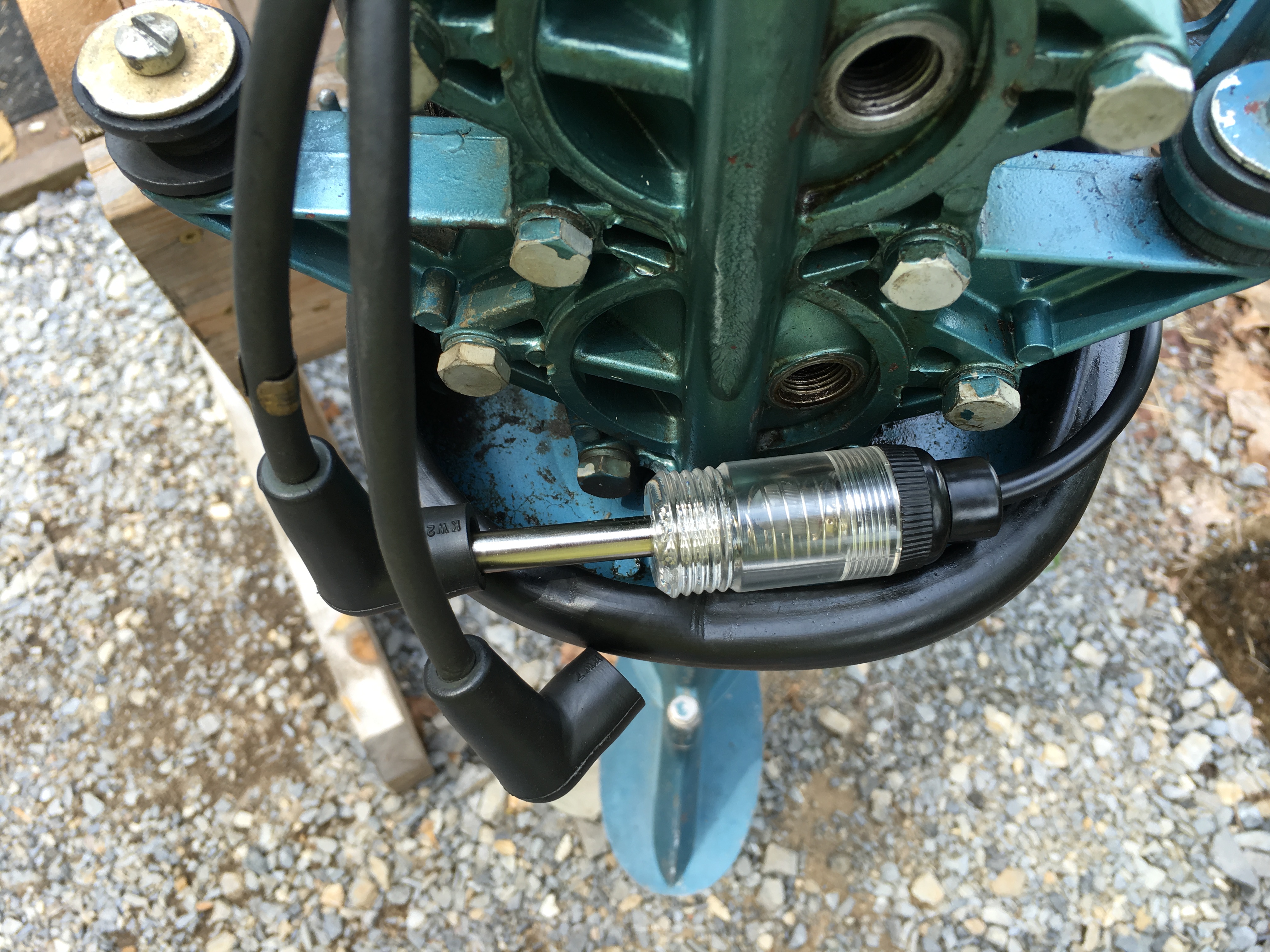
One other thing I learned today is that I had to switch the polarity of my wires to get the module to fire on the this omc engine on my other omc engine they were the opposite. Whats great about the way I am mounting them is you just switch the black and red wires from ground to the small positive primary wire that goes to coil. Also check out the cheapo spark tester in pics if it won’t light up when you spin flywheel clockwise like normal try spinning it backwards and if it lights up wires are reversed and need switching. Now that redneck technology at its best.
I am going to post more on my how to’s and where I am getting parts later. I think I can build these for less than 2 dollars a piece. Got parts on order going to build some more on the cheap and test them then report back. Right now waiting on parts.
Joe
ps take a look at the first pic with red and black wires those are the ones you reverse.
Attachments:
https://SecreLocal.com - - No Verify - Anonymous Adult Dating -
-
AuthorPosts
- You must be logged in to reply to this topic.