Home › Forum › Ask A Member › 1957 15hp Evinrude
- This topic has 23 replies, 12 voices, and was last updated 5 years, 11 months ago by
joesnuffy.
-
AuthorPosts
-
May 4, 2018 at 10:19 am #75321
I bought the tool from Frank also. It`s worth it`s weight in gold.
May 4, 2018 at 11:39 am #75323You guys have pretty much talked me into getting the tool. I do have his ring that goes around the coils to place them correctly and his 180 degree points adjuster tool for a 28hp up to ? and really like them. Bill I didn’t come up with the modules information Debe here did the whole thread can be read right here.
viewtopic.php?f=2&t=1050&hilit=modules
I am currently working on a list of parts I am using and a how to plus testing what I build that’s key also testing to make sure they hold up and engine performs well. These ones I have built for this 1956 seem to be working very well but I need to get the motor on a boat and make sure it winds up to high rpm’s and they don’t break down or fry and stop working so that’s next. I am also working on a finished product with a heat shield and insulation the rest the info below is how I am making them for testing purposes its quick and easy I can solder one together in 10 minutes max.
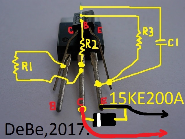
MODULES FOR TESTING PURPOSES BELOW:
Here is how I am making them for Evinrude/Johnson 2 stroke 2 cylinder motors I use part of the old points to make them but I only screw my module to them and it could easily be unscrewed and the original entire set of points assembly put back. This is from page 22 of the thread above.
Keep in mind these are test modules not sealed with clear silicone or epoxy etc. They are a work in progress.
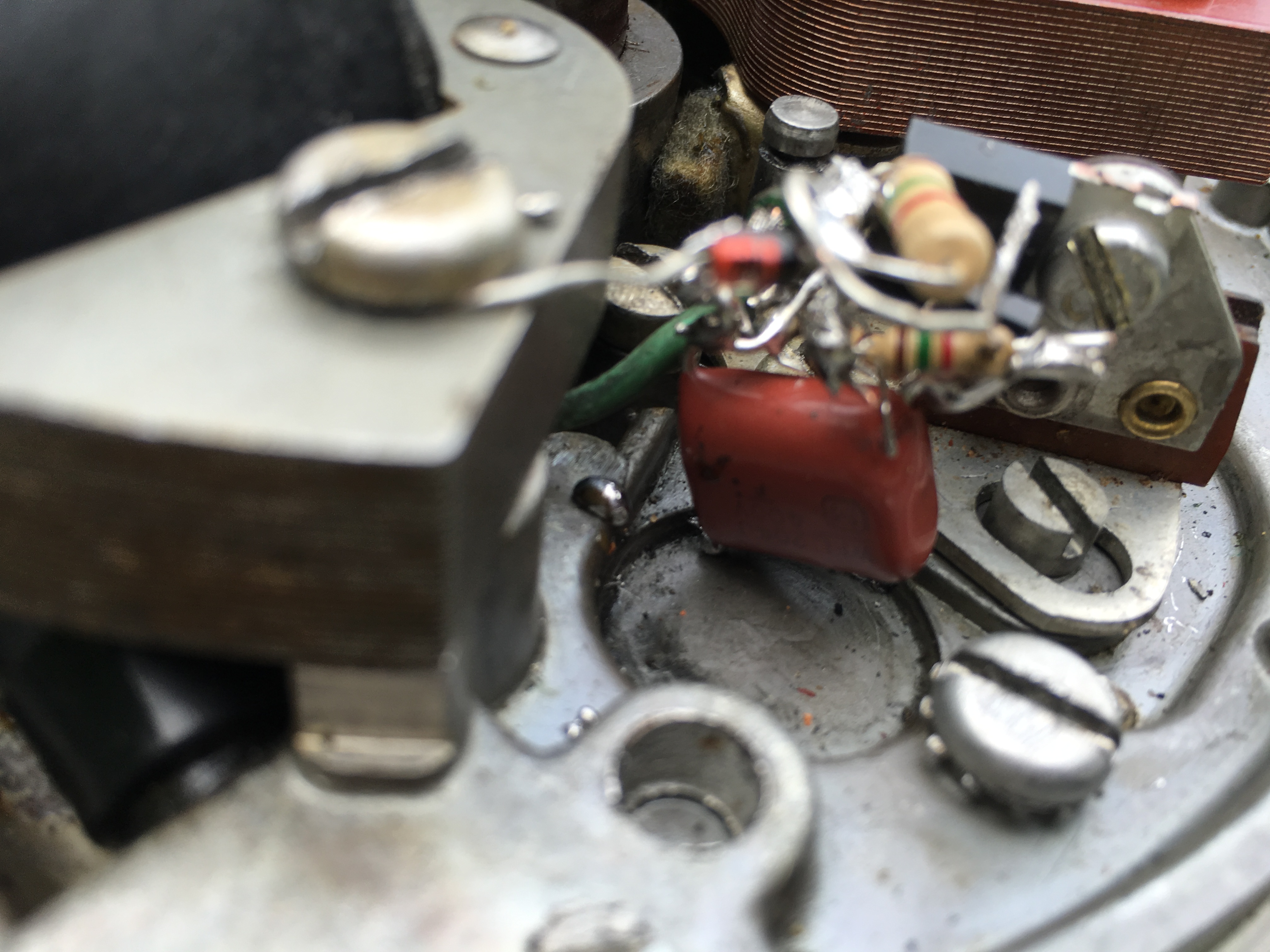
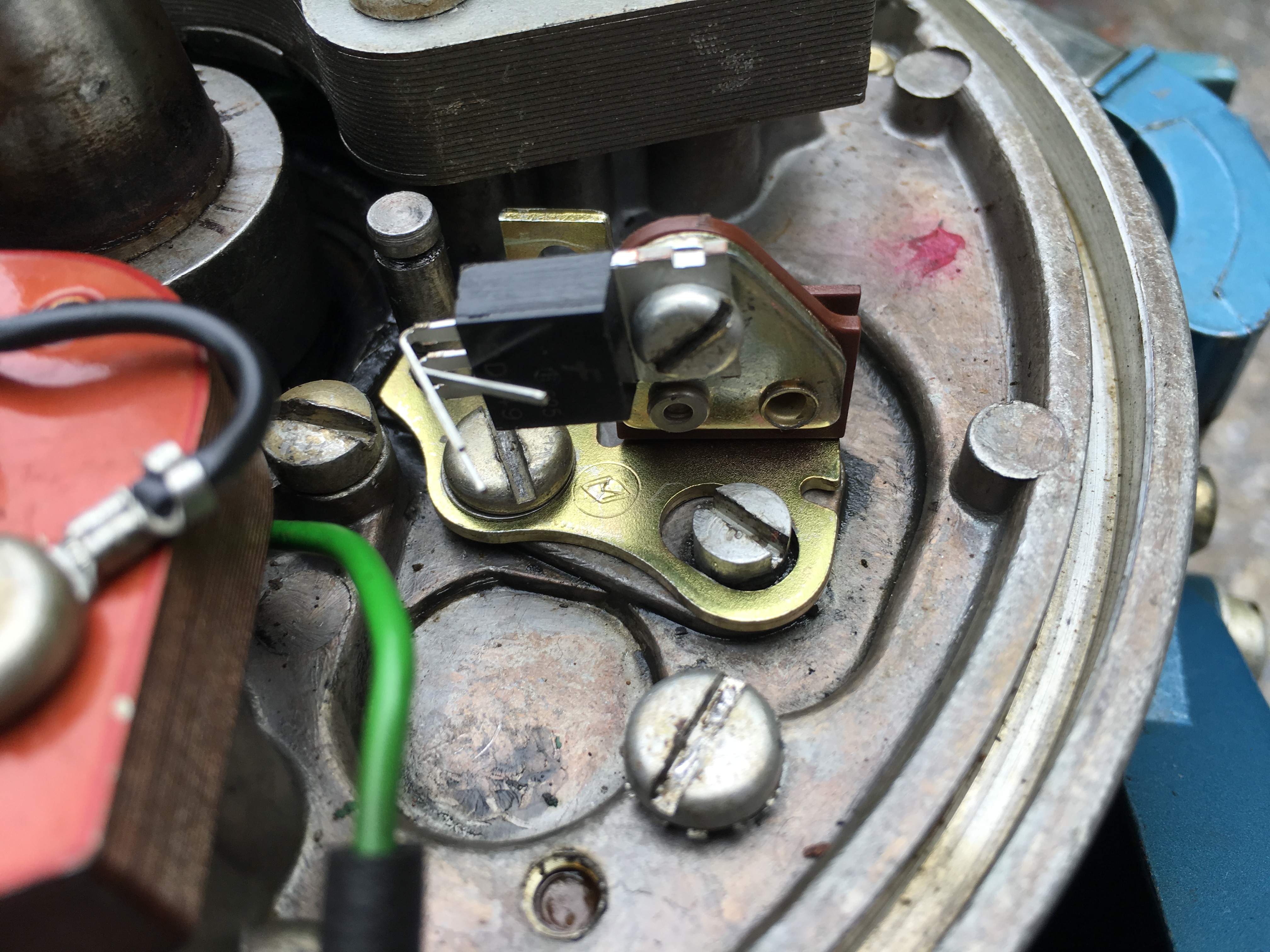
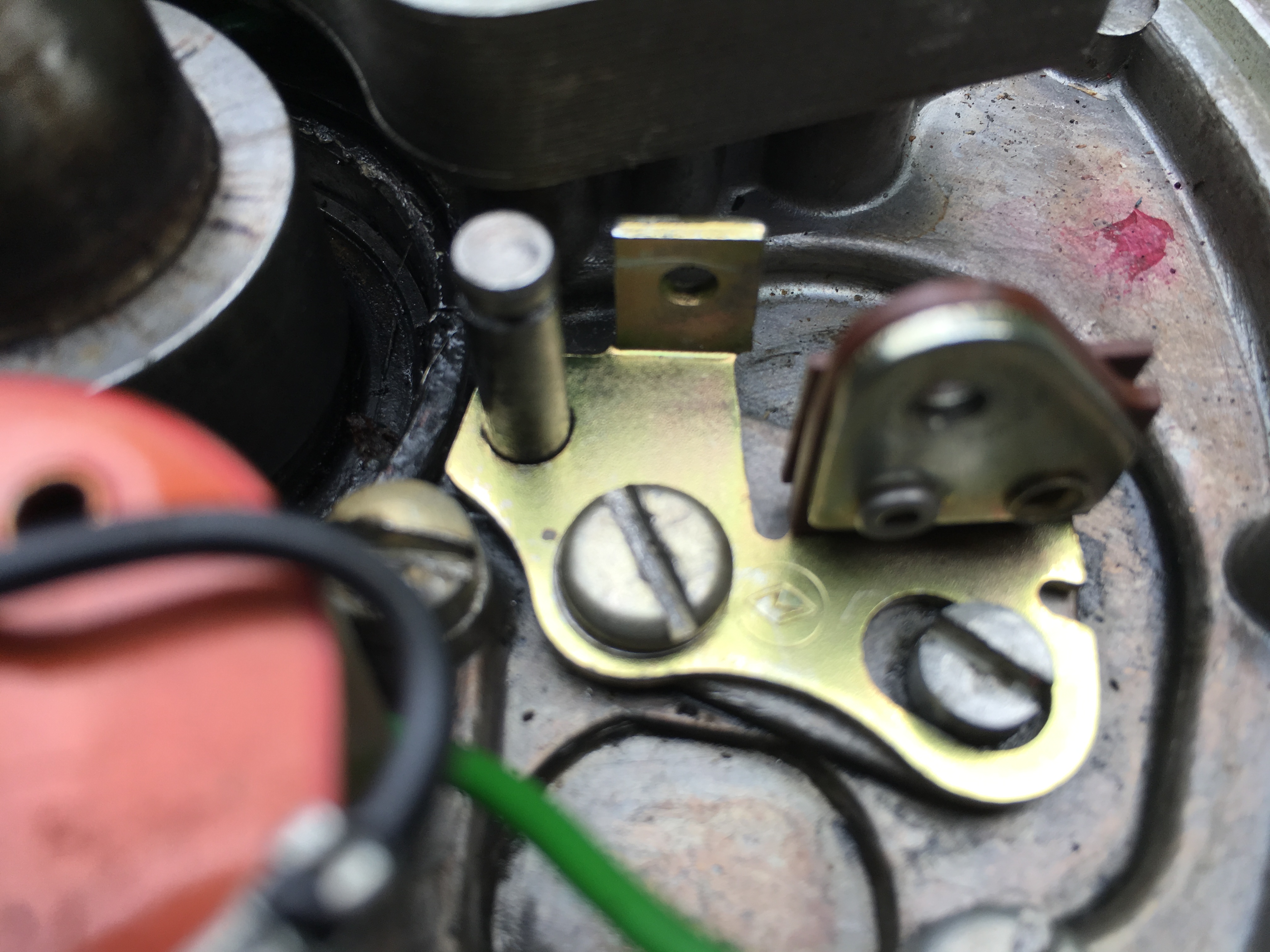
I worked on my 1956 Evinrude 15HP today and made some great strides. I figured out how I am going to mount my transistors for 2 cylinder omc motors 2 stroke of course. Take a look at the pics. Using half a set of evinrude/johnson points is how I am doing it. The half set of OMC points are already insulated against ground and they have metal tapped for screw plate on them for my heat shield. Best part of all is all the original screws can stay in the engine if you desire. If someone wants they can swap it right back to a points system with a new set of points and condensers since all original omc screws are in place. You can see how I mount the transistor to a half set of omc points. I took a pic of only the transistor on the half set of points so you could tell how I am doing it I then took it back off motor and soldered everything to the transistor and then screwed it back on.
One other thing I learned today is that I had to switch the polarity of my wires to get the module to fire on the this omc engine on my other omc engine they were the opposite. Whats great about the way I am mounting them is you just switch the black and red wires from ground to the small positive primary wire that goes to coil. Also check out the cheapo spark tester in pics if it won’t light up when you spin flywheel clockwise like normal try spinning it backwards and if it lights up wires are reversed and need switching. Now that redneck technology at its best.
I am going to post more on my how to’s and where I am getting parts later. I think I can build these for less than 2 dollars a piece. Got parts on order going to build some more on the cheap and test them then report back. Right now waiting on parts.
Joe
ps take a look at the first pic with red and black wires those are the ones you reverse if your not getting fire to spark plug.
Attachments:
 May 4, 2018 at 12:00 pm #75324
Have to echo Bill’s comments on Frank’s o-ring tool, it is marvelous!
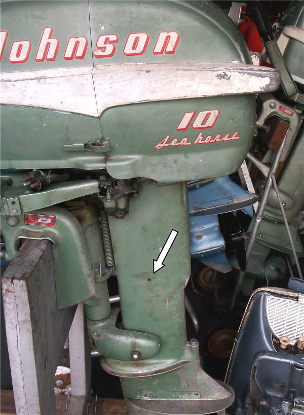
I use many pressure tanks, all are tight.May 4, 2018 at 12:44 pm #75326quote joesnuffy:I do need some guidance on replacing the o-rings in the fuel connector. I would like to fix it next but since I only have one pressure tank I kinda don’t want to spend the money for the tool. If I can’t fix it I could mail it to someone that has the tool. I need to know what type and size o-rings I need?? and maybe a brief how-to do it. Thanks in advance.Also does anyone know what that small hole is on the mid-section that is spitting out water? Is that a modification?
Thanks,
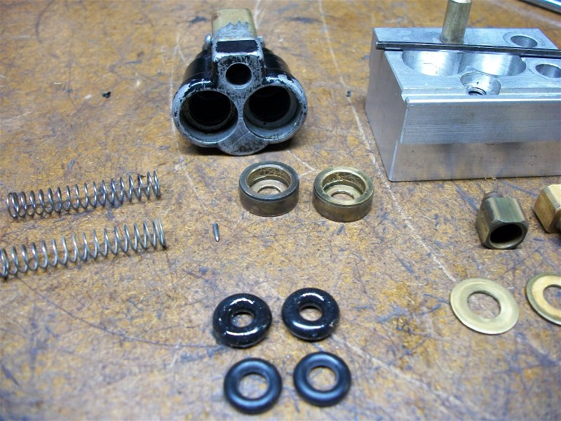
JoeYou’ll love that tool. Here is a brief how-to do it that Frank still has up on his website: http://www.franksoutboardtools.com/fuel … xture.html
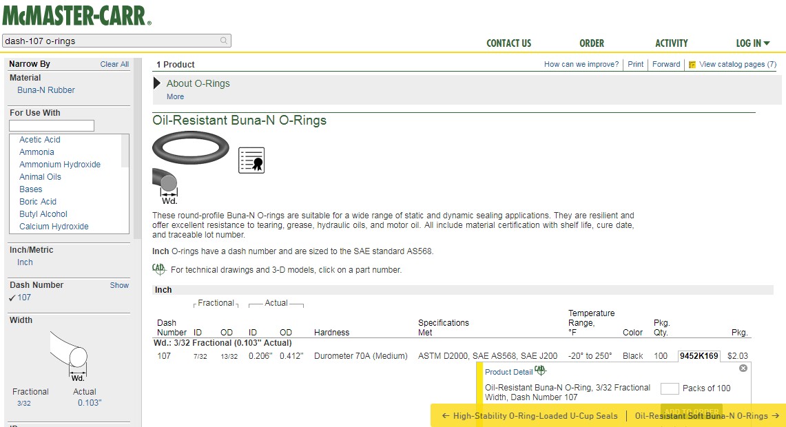
As Richard says you’ll get a couple o-rings with it but here’s some info on those for future reference: OMC #301824 – don’t get the Sierra version, it looks like they’re still offering fat ones that don’t work well. McMaster Carr has them by the 100 bag and they work very well.
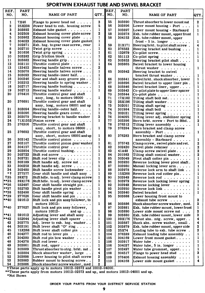
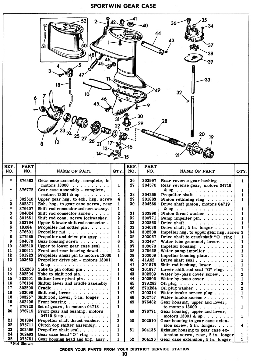
If you’re asking about the hole in the picture it’s the upper water tube grommet tab/ear hole. Grommet is worn/dried out and water is getting past it.
Attachments:

 May 4, 2018 at 12:55 pm #75327
One of my customers told me this, and I was somewhat skeptical. But I tried it and it worked. Your mileage may differ.
The suggestion was to stack two of the (Mcmaster) o-rings in each cavity. It does give a more reliable seal, especially when unplugged from the motor. Of course you are supposed to relieve the pressure before unplugging it, but—well you know.
May 4, 2018 at 12:57 pm #75328Thanks Steve and Frank that is good information. I contacted Richard and am waiting and I will get the tool I wouldn’t want to mess up my connector their expensive and hard to come by. That is the hole I was referring to it sprays water out of it and it actually soaked my pants while I was standing near the idling motor.
Joe
May 7, 2018 at 11:00 pm #75524Got my dual fuel line OMC tool today from Richard that is used to change leaky O-rings. It works superfantastic made it a breeze for me on my first dual fuel O-ring changing.
Thanks Richard,Joe
May 8, 2018 at 4:25 am #75542Yeah that would be cool to make! Teach us master yoda.
May 8, 2018 at 12:26 pm #75547I built a Red Atom styled module yesterday for 75 cents all from the same supplier. It has some of my tweaks I have been working on to make it work better for older Johnson/Evinrude 2 stroke 2 cylinder outboards that came with points and condensers. I am going to have to see if I can improve my pictures some how for my how-to of building them.
I am going to call it the "75 Cent Module" if it works. I will hopefully build a second one tomorrow which is Wed don’t have time today and put both of them in a 2 stroke 2 cylinder Johnson motor to see if they will work well then take them out on the water for a test.
Joe
May 9, 2018 at 1:09 am #75595That water leak in the exhaust is from an improperly seated water pipe (Copper tube) scrunching the 0302497 water tube grommet which makes it leak and may cause the engine to overheat. . . 🙂


-
AuthorPosts
- You must be logged in to reply to this topic.