Home › Forum › Ask A Member › Testing timing of Red Atom Modules
- This topic has 35 replies, 9 voices, and was last updated 5 years, 6 months ago by
oldfogeyuk.
-
AuthorPosts
-
May 27, 2018 at 5:30 pm #10061
I am starting my topic with the end point first and I am thinking out load sharing what I have been testing for Red Atoms. I tested the timing on them yesterday using an older OMC motor since they have the pre-drawn lines on flywheel and magneto plate when points should break. I set the points to those lines to break as they should then put in modules and checked to see when they fired to see how close they were.
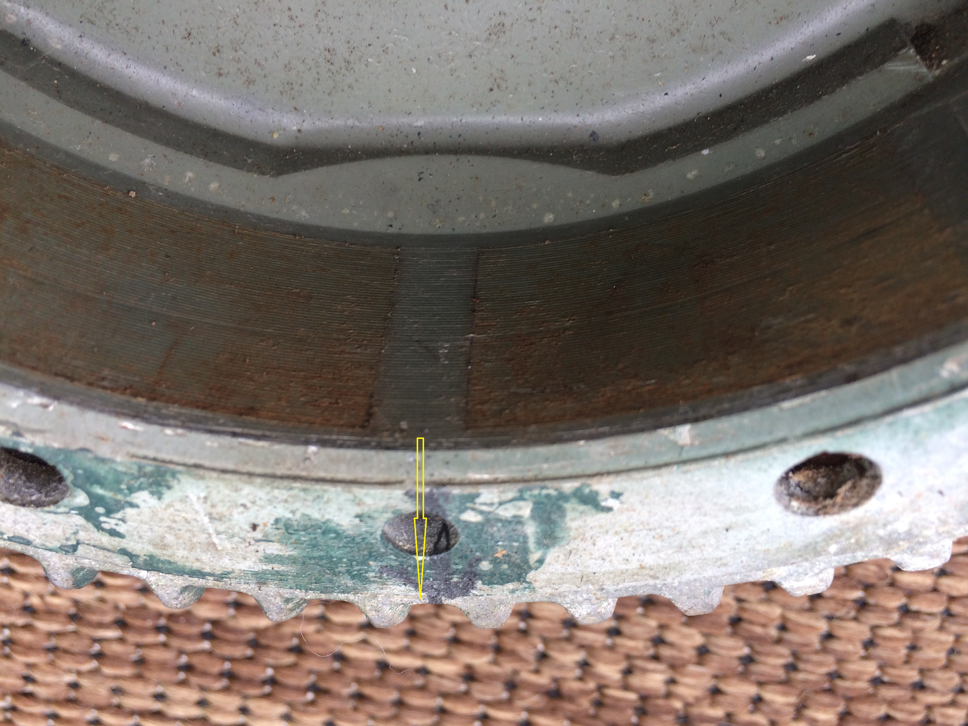
Some folks on here will say well we all knew this but I didn’t so I am sharing what I learned for the Red Atom molules. We have all worked on motors of different brands and the flywheel is not marked to show when to set-up the points to break at exactly 180 degrees apart. The line on my OMC flywheel where points should break was in the exact center of between the two magnets. What I discovered yesterday was that the electronic modules fire between the space between the North and South magnets which is exactly when the points do also. That space between North and South magnets is also lined up with center of laminate that coil mounts to when engine should fire. The coil helps to monitor when to fire the electronic modules by sensing when the space between the North and South poles appear. I am showing a 12hp West Bend flywheel that I have drawn a yellow line on to show when the points should break. I used it because it did not come with a line on it. The line can easily be drawn to other side of flywheel using a straight edge to get the other 180 degree mark where points should open very close using straight edge. The engine can be placed at TDC and the mark you put on flywheel can then be drawn to somewhere on the part of magneto that lines up with the mark you put on flywheel that should be where points break. It is already drawn on the magneto plate in the 3rd pic below for OMC its where the 2 lines are. Once you draw your lines on a motor that doesn’t have them and time it with points to those line you can the swap the the electronic modules to see if they fire at the right time. Module timing can be varied see what is written below.
Some folks will say you can’t alter the timing of the motor without moving the magneto and that is true with points but with the modules it is and it isn’t. When you move the magneto with the modules it does change like normal with using points. But when the modules are built I believe you can change the exact time when the engine fires electronically slightly by changing the resistor values below. Remember I said that the coil acts as a sensor looking for the space between the North and South and then produces the spark. Here is an example of 2 modules that were sold one was Brown and one was Red. The R’s are resistors and the C is a capacitor. Notice how you are adding and subtracting about 500 ohms from each module. I didn’t come up with these values the module manufacturer builder did and Debe took the time to take them apart and share his findings. All I was doing was making sure timing was about the same for them as points. The modules sense the gap of North Pole to South pole break that distance between them is when the module triggers by adding less ohms to resistors I believe the fire would occur sooner with the coil acting as a sensor it would sense the gap sooner due to less resistance on the resistors.and since Briggs motors timing does not vary I believe they fired with more BTDC less resistance on R1 and R3 would make it fire sooner because the sense the gap between magnets sooner. A person could always add or subtract like 100 ohms in correlation to each value below using a timing light to help fine tune their timing plus or minus I would guess like 8 degrees max which doesn’t need to be done for OMC the Red Atoms fired correctly during my tests I was just saying if you had a motor that needed altering or maybe were going to build a race engine that you wanted to to gain more BTDC firing.
Brown Module Atom Briggs and Stratton usage
R1 = 1000 ohms
R2 = 2100 ohms
R3 = 1000 ohms
C = .47Red Atom Outboard usage
R1 = 1500 ohms
R2 = 1500 ohms
R3 = 470 ohms
C= .47Example different values of a test module might be to alter base timing
R1=1300 ohms
R2=1800 ohms
R3=700 ohms
C=.47I did build a working red module yesterday for 35 cents that worked. I am going to hopefully be done testing soon. I have noticed that polarity for the DIY red atoms has to be changed for different coils used in OMC engines. I believe this happens because of different manufactures wind the coils in different directions so to cure this you would be swapping where the red to black wires are soldered. One goes to small positive wire of coil the other to ground. But keep reading below how I am building them.
I believe that the coil ground and positive wire can be reversed to accomplish the same I just have to test my theory. They would just be lengthened a tad if they need swapping. The reason this would be better for the modules I am building is I am trying to come up with a solution using a set of the old omc so you just screw them in like normal . Where positive small wire actually screw to the electronic module transistor which is mounted to half of an old set of points and the other small wire from coil to ground as normal. That way all wires screw in like normal and for motors that have kill wires that go from one set of points to the other the wires would screw to module just like they would points.
 May 28, 2018 at 5:46 am #76884
So far I’m intersted in this, its looking good and is kind of inline with an idea I’ve been tossing around for my tn engines I’m building, keep it up I think your on to something.
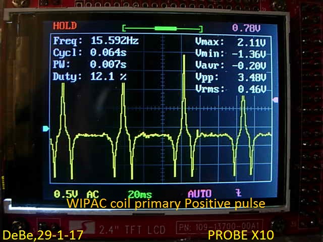
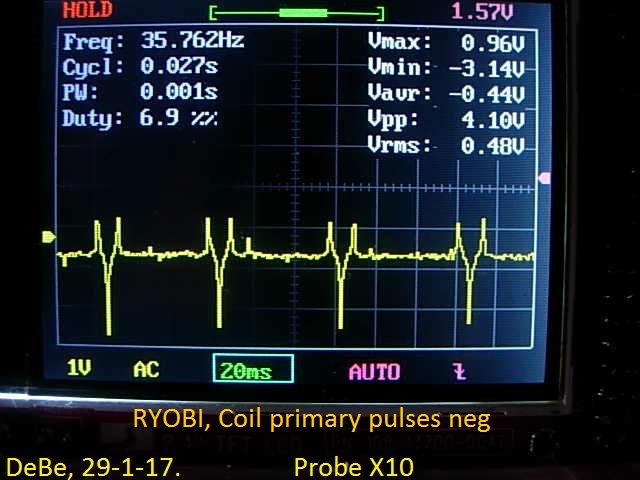
May 28, 2018 at 8:48 pm #76916Its good to see you experimenting with these modules. The ign coils will either have a positive or a negative pulse, this determines the polarity to wire up the module. For example Seagull outboards use Wipac or Villiers coils & they are 2 different polaritys. Picture of CRO patern of 2 diferent coils.
 May 31, 2018 at 2:21 am #77105
Nice description of of your observation and findings, I enjoyed reading your progress in the development of your modules and possible variations in timing .
HansMay 31, 2018 at 3:03 am #77110Thanks guys.
Joe
May 31, 2018 at 8:41 am #77115Good research and description with photos of what you have been studying.
Thanks, Jim PSB"Some people want to know how a watch works, others just want to know what time it is"
Robbie RobertsonMay 31, 2018 at 2:27 pm #77133Debe,
Thanks for the help. I am going to get a lot of pics today.I have had more luck with the BD 649s than the 1071s right now I am trying the TIP102s with good results since their readily available where I am getting parts.
I have noticed that OMC coils also have different manufactures and different positive and negative pulses produced so the polarity has to be reversed to module to get spark while motor is spinning in clockwise position. Is that caused because the windings in coil are opposite??
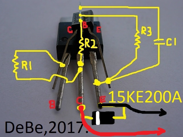
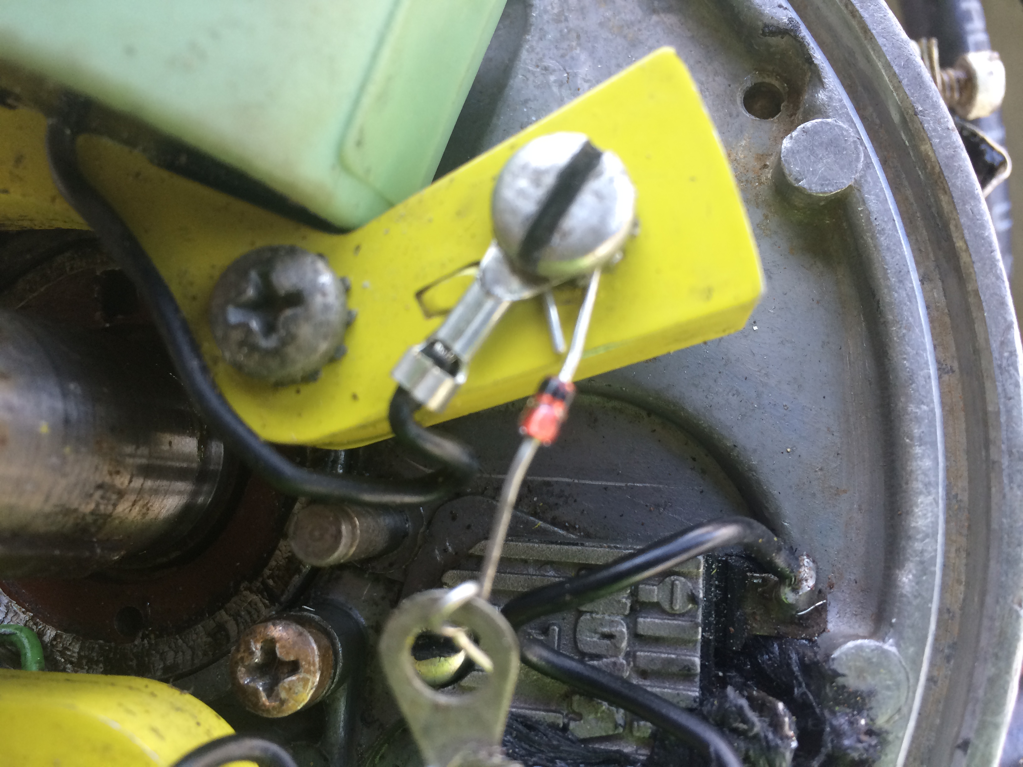
If motor does not spark clockwise I then spin it counter clockwise to see if spark is attained then I know to reverse the polarity to get spark while motor is spinning in clockwise direction. Some motors will have 2 different manufactured coils in them due to a past coil swap so it might be that each module has to be wired in reverse polarity for polarity to get spark while motor is spinning in clockwise position from both coils. I do this by just switching the small wires from coil the one that goes to ground I put it to the middle leg(leg C) of the larger transistor (BD649,2SD1071,currently trying a TIP102 with good results) and since I am screwing the larger transistor to the half a set of points the metal on the larger transistor has direct continuity with the middle leg of larger transistor (leg C). I then attach the smaller wire that would go to the points instead to ground. The wire I use from ground to the actual module leg E I do so using a one direction mosorb diode with the stripe on diode being grounded and the other side of diode going to leg E and that protects the circuit it also works on Nova2s and protects them while allowing them to work. Here is a pic of a diode being used to protect nova2 circuit its not a mosorb but it shows how I am doing it for them to protect them the black wire in photo is attached to diode goes to the negative side of nova2 and circuit fires as it should I have tried it with the mosorb and it works. Sorry for the crude pic but it shows how to do it.
here is where I get my 1 direction mosorb diodes just ordered 60
https://www.ebay.com/itm/20PCS-1-5-KE20 … 2749.l2649
One question I have is it it ok to use the metal of larger transistor instead of the middle leg as a point to attach the positive pulse wire??
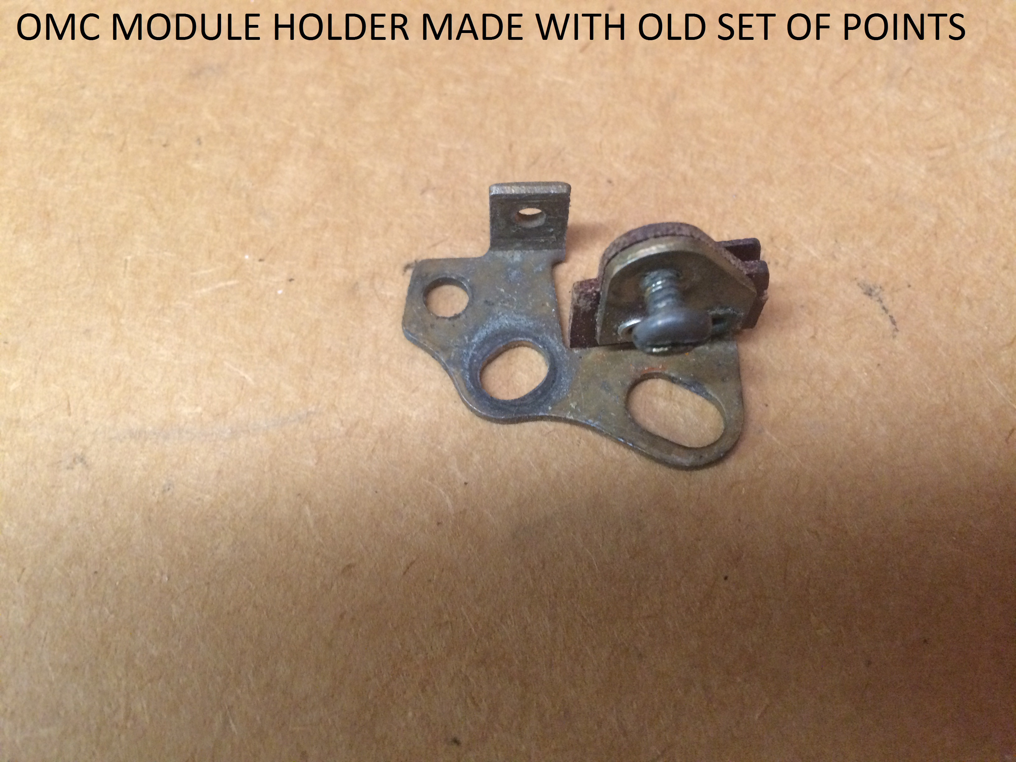
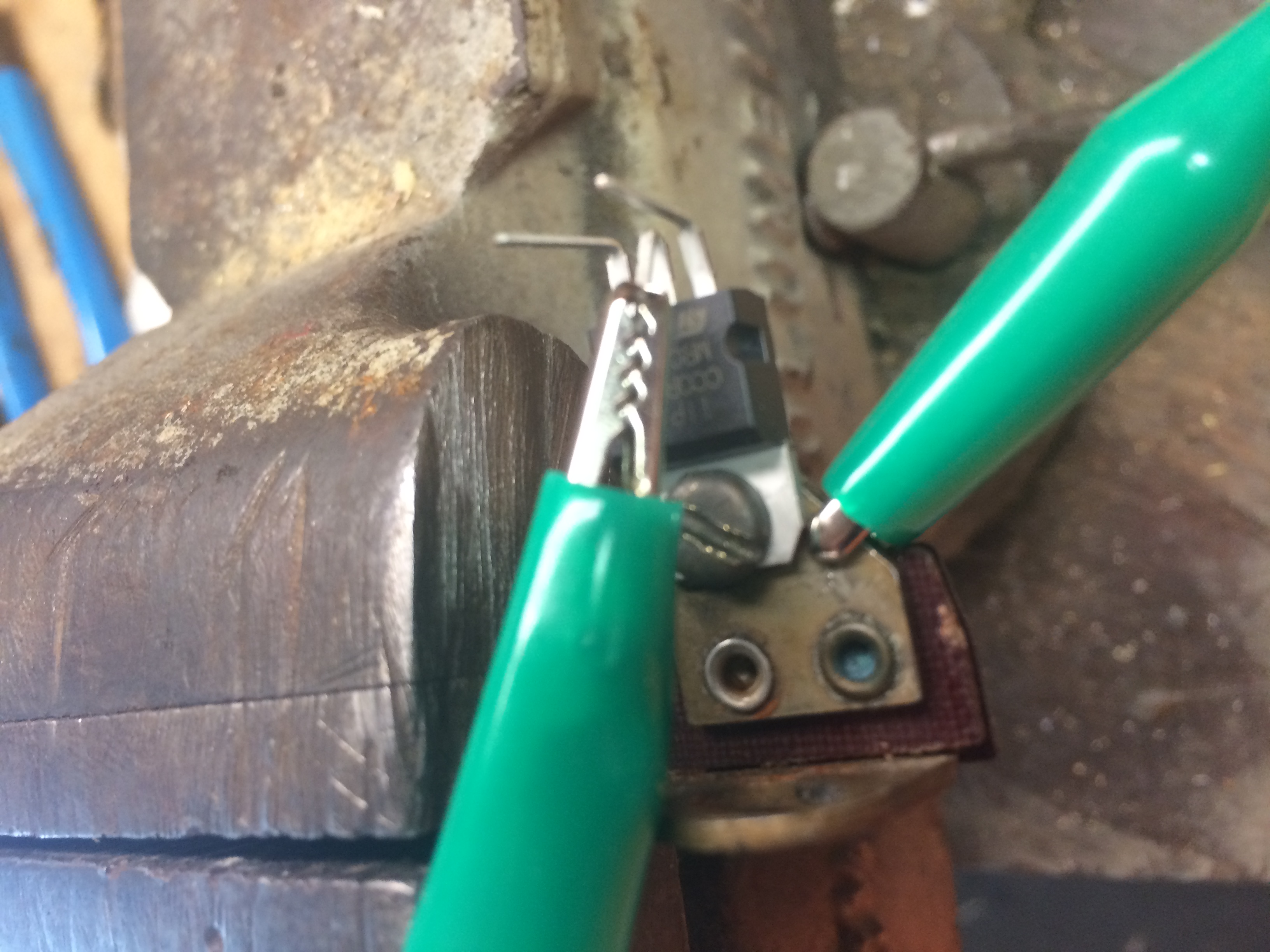
Here is what I attach module to notice the screw would go through the hole on larger transistor along with one of the smaller wires from coil.
continuity
This is how I attach small wire from coil to middle leg of large transistor you can also see the mosorb diode screwed to ground on one side and going to leg E or larger transistor.
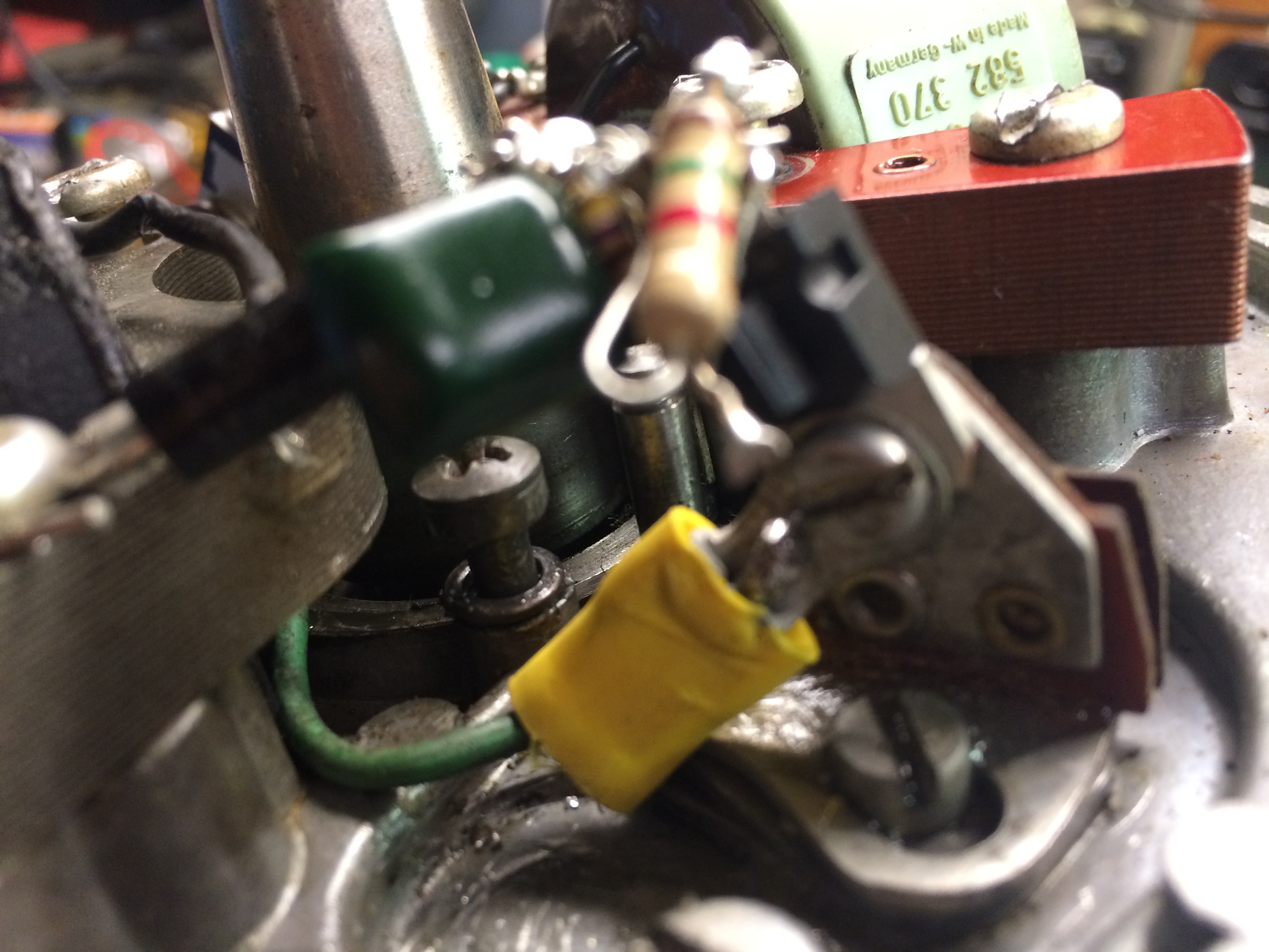
Again sorry for the crudness of my work and pics but it is experimental.
Joe
May 31, 2018 at 6:24 pm #77148Looking good if your testing with the flywheel on you dont have massive room to work under there anyway so it will be crude until a unit is built after testing that is all soldered and compact. Its the nature of the beast.
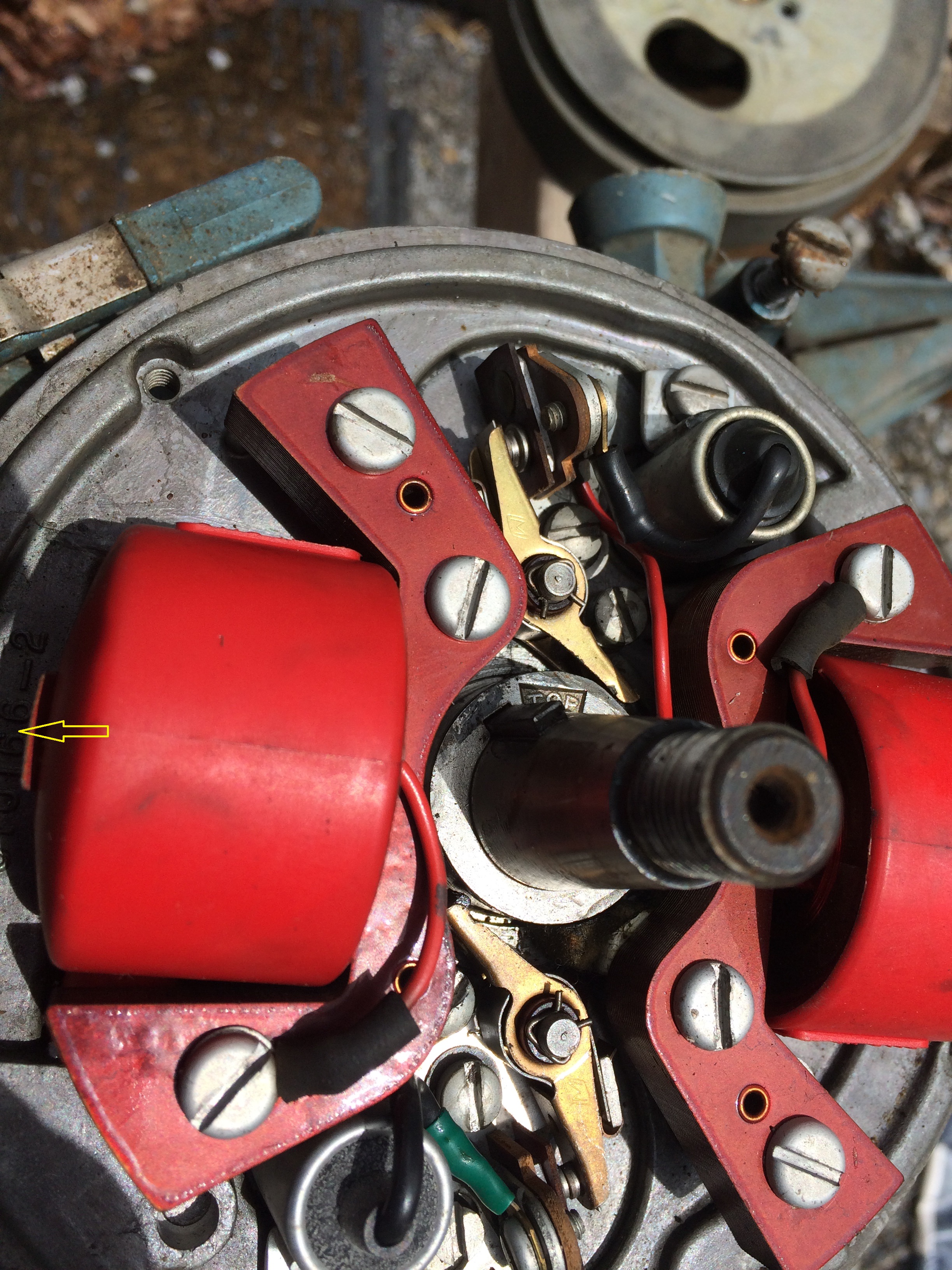
May 31, 2018 at 7:53 pm #77156I made a plate out of some Bakelite and mounted the Atoms on it. The plate with the Atoms is mounted outside the motor using the spark coil mounting screws. All I had to do is remove caps and the moving point thing. The point base was left in and was used as a terminal block. The plate also had a piece of terminal block for the spark coil connections.
After about 100 hours one Atom went AWOL so I went back to points. I might ..this winter…make a couple of point eliminators on that bakelite plate and pot it somehow.
May 31, 2018 at 9:29 pm #77160Hadnt thaught about reversing the wiring of the coil primary, but it seems to work. Using TIP102 & BD649 transistors the Mosorb or TVS will need to be a 1.5KE91 (clamps voltage spikes at around 90V) its a 90V 5W TVS, & this will get quite warm on some coils. This is required as the transistors are only VCEO 100V (Collector to Emitter breakdown voltage). It took me a long time to find a reliable transistor to handle the High voltage spikes on the primary windings of the ign coils. The 2SD1071 has a VCE of 300V, even that did not like the Wipac coil on a Seagull motor, that was the reason for adding a 200V 5W TVS. Using transistors with too low a VCEO will cause reliability problems. This is probably why the Nova modules fail. The modules when finished & tested do need poting, as vibration will eventually cause problems with the wiring of the components.
-
AuthorPosts
- You must be logged in to reply to this topic.