Home › Forum › Ask A Member › Testing timing of Red Atom Modules
- This topic has 35 replies, 9 voices, and was last updated 5 years, 6 months ago by
oldfogeyuk.
-
AuthorPosts
-
June 5, 2018 at 4:40 pm #77465
I’m new to this discussion thread, but I think I can be of some help.
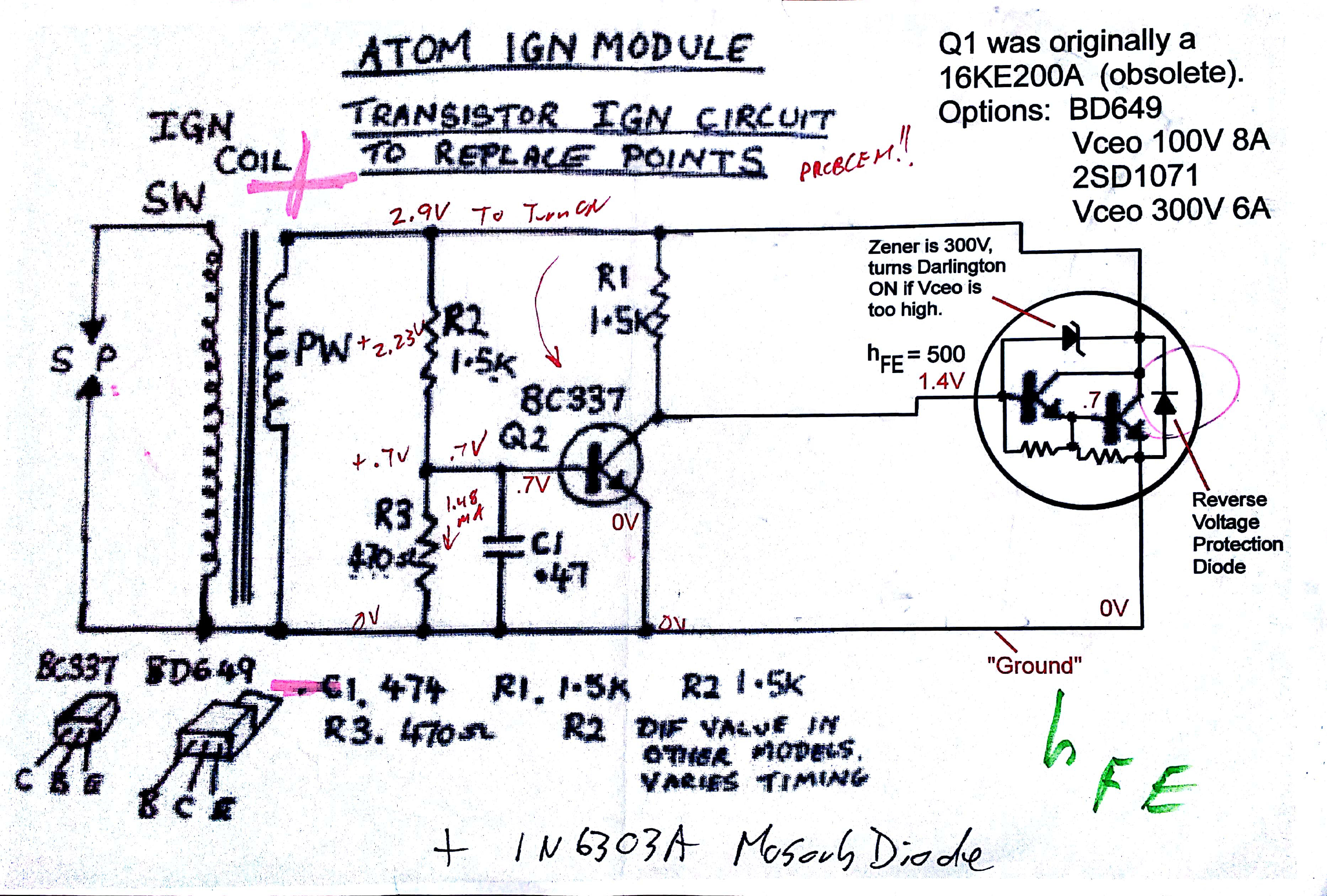
Please look at the attached file: AtomRedSchem_1.jpg Is this the schematic you are working from?
I think it is.Please note that I changed the schematic symbol for the power darlington…..the original symbol was not
correct, and you can’t understand how this module operates if the schematic symbol is not correct. I think
the symbol I used was for a 2SD1071.Anyhow…. all solid state "points replacement" modules (be they Atoms or anyone elses’) …they all face
the same dilemma. In your original magneto with the points closed, the voltage across the primary winding (PW)
is ZERO, as the points short that voltage out completely. If the "switch" in your solid state module did the same,
you would have NO VOLTAGE to work with, and you could not turn the "switch" off. Nasty little design problem there.The "solution" to that dilemma is that power darlingtons are VERY INEFFICIENT; they waste a lot of voltage
across them, even when "on" to the maximum possible. When the primary coil is generating that big positive
voltage spike, the power darlington does not completely short it out (like your points would do). Instead, you
get a voltage drop across the power darlington, porportional to the current that’s going through the device.
According to the values in this schematic, when the voltage drop across the power darlington reaches about 2.9
volts, Q2 will turn on, and short out the Base of the power darlington, turning it OFF (i.e. "opening the points").When using points, the cam opens your points when the positive voltage spike is at maximum voltage, or a little
later (because current lags voltage through an inductor, and you want to delay the points opening until you have
maximum current through the primary winding……which occurs slightly AFTER the voltage peak. But, in contrast,
the ATOM modules are "voltage drop" triggered, somewhere during the RISING SLOPE of the positive voltage spike….
about 2 to 5 degrees BEFORE your points will open up. (I’m just guessing here…..but it’s probably a good guess.
Has anyone ever measured this timing difference? Apparently someone has, because that seems to be the
content of this thread….trying to delay the spark timing generated by the ATOM module.)If that is your goal, you have to realize the following:
1) The values of R2 / R3 set the "current trip" threshold of when the power darlington will turn OFF.
However, because of the steepness of the positive voltage spike, changing R2 or R3 will only alter
your timing by about one degree, at best.Also, when your RPM goes up, the positive voltage spike will greatly increase in amplitude. When you
have points, this doesn’t change the timing. But, because the Atom design’s timing is based on a current level,
this will cause the Atom design to "trip" earlier at higher RPM, because the primary positive voltage spike
will have a higher peak value. This isn’t serious, probably the timing will advance by about 1 degree at
most, which is why nobody seems to have mentioned this before.2) You can increase the value of C1….and that will delay the turn off of the Power Darlington a bit. But,
if you increase C1 by too much, you won’t turn off the power darlington at all (especially true at lower
RPM, when the positive voltage spike is at lower amplitude…..this might make the module stop working
completely at lower RPM, long before you see the delay you are looking for.) I expect increasing this
capacitor to .68uF (or thereabouts) will delay your spark a couple of degrees, but I don’t know what other
side effects it might give you.3) At low RPM, your "positive voltage spike" might only be 5 or 6 volts, and the power darlington is wasting
about half of that voltage, decreasing the spark intensity at low RPM by about half. This might require
you to spin the motor faster to get it to start, compared to when you had points installed. This seems
to be a design problem for all of the currently existing "points replacement" designs I’ve looked at so far.4) Any timing delay other than the simple "R-C" delay here (formed by R2/R3 and C1) ….any other type
of timing delay device will require a steady source of voltage (perhaps 3.3V or 5V)….which this design
currently does NOT have. To derive such a power source from the spiky voltages seen across the
primary windings would be a bit of a trick, to say the least.**** Who is measuring these timing delays? Are you using an oscilloscope, or just a timing light on the
marks you are putting on the flywheel? What difference do you see between the points timing, and the
timing you are getting from these Atom modules? By exactly how much do you want to change the
timing of the Atom module?***** Also, why are people looking at putting some kind of protection diode in this circuit? The 2SD1071
appears to be able to handle 300V, and has a reverse voltage protection diode built-in. (Or, are you using
something other than the 2SD1071?) If so, then what is your intended purpose for the protection diode?
What are you trying to protect against? What parts are failing when this diode is NOT present?–Bill
Attachments:
***********************************************************************
Bill Mohat MS/CIS, BSEET, CCNA"You can avoid reality, but you cannot avoid the consequences of avoiding reality." --Ayn Rand **********************************************
June 6, 2018 at 1:42 am #77504

This is the timing diference betwean the orig points & an Atom ign module slightly advanced. Not worth worrying about as ive had no problems with starting or the running of my outboards or lawn mower. If I was concerned then I would just shift the base plate slightly to alter the timing.
June 6, 2018 at 1:50 am #77505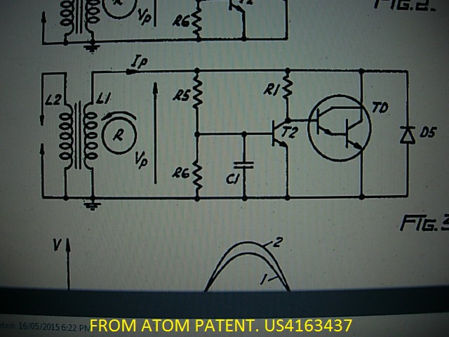
If you look back in this thread you will find the circuit we are using, you have found an early attempt. I have de constructed several of these modules & they are the same circuit basicly as figure 3 in the Atom US patent. Its US4163437 if you want to read about the original concept. This concept using Darlington transistors is used in just about every electronic small engine ignition coil, they are built inside the coil.
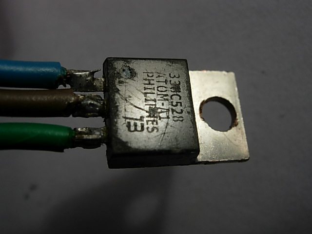
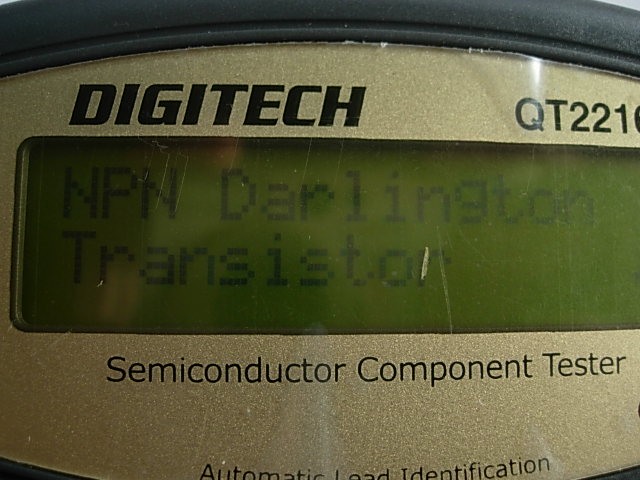
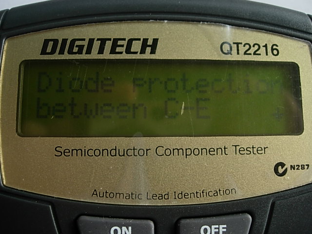
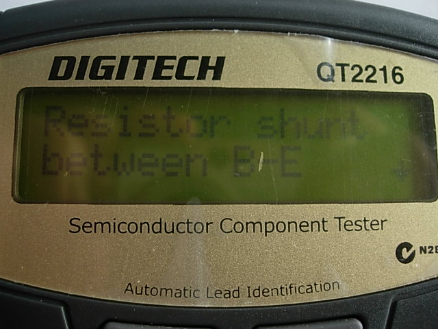
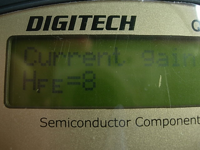
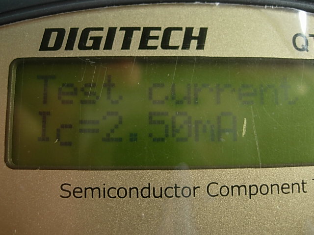
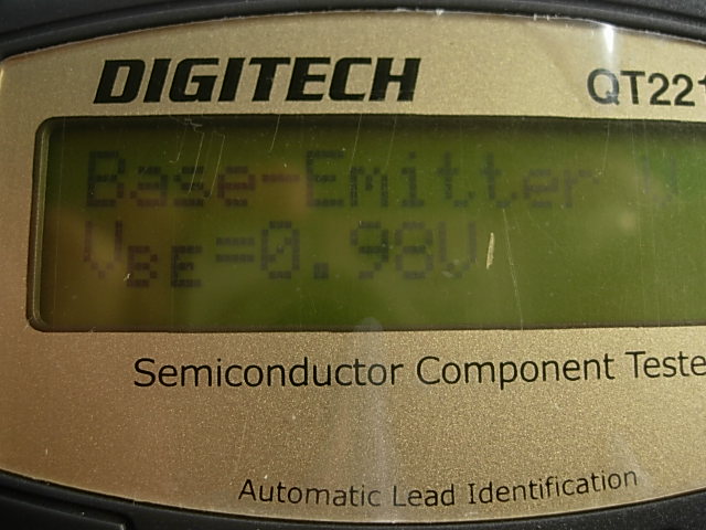
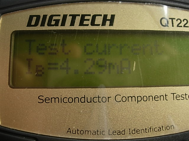
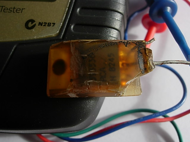
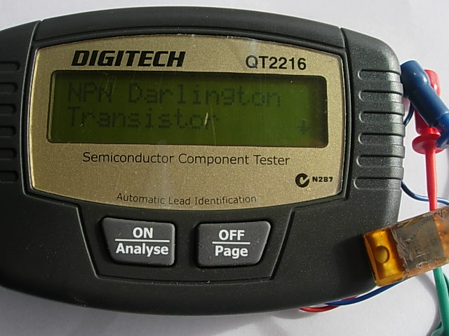
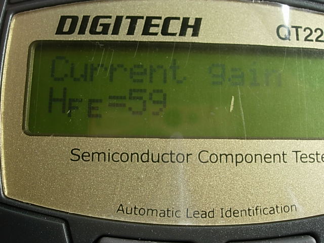
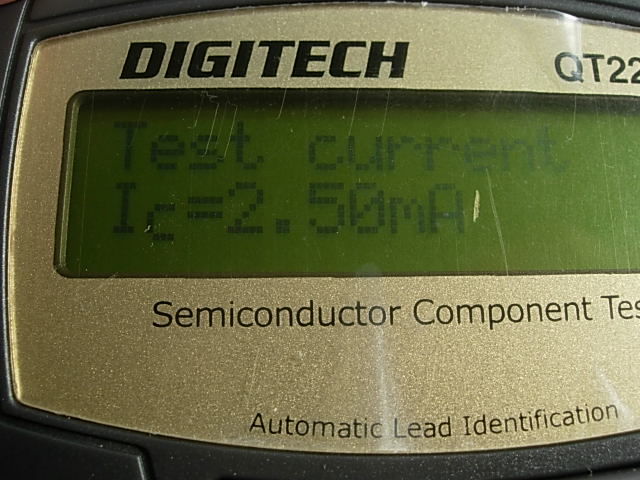
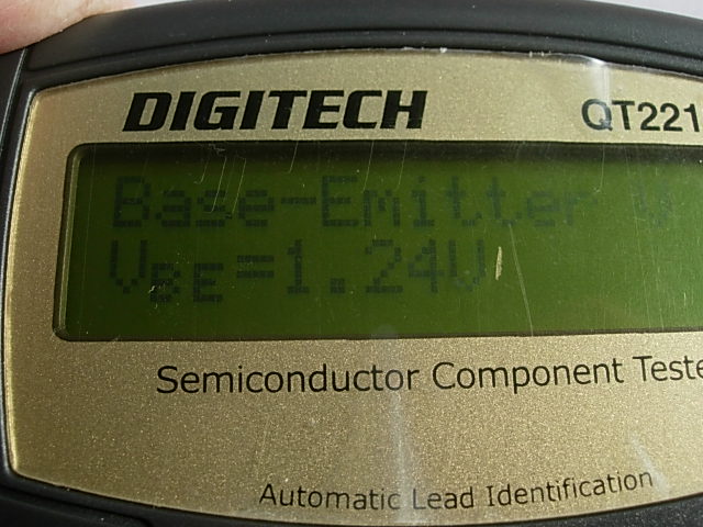
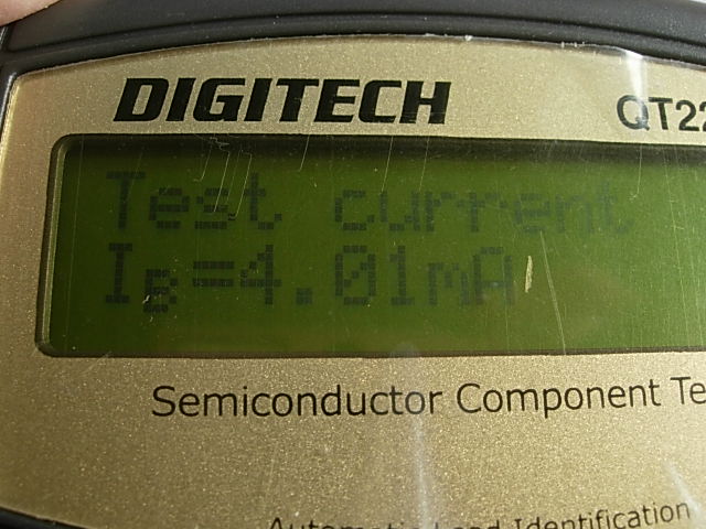
June 6, 2018 at 1:57 am #77506This is the original Atom transistor specs that I could test, They were obviously custom made for the module manufacturer. The reason ive used the TVS to protect the transistor as some ignition coils would damage the transistor 2SD1071. This combination ive found the most reliable.
 June 6, 2018 at 2:02 am #77507
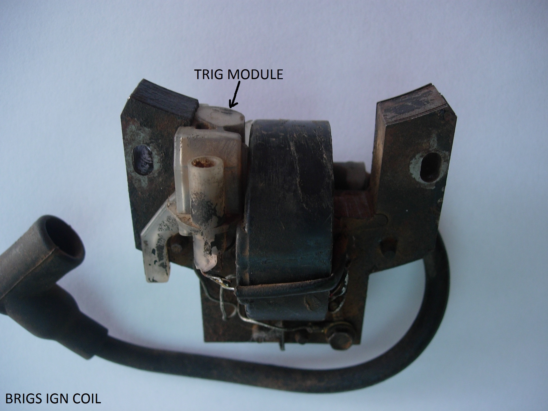
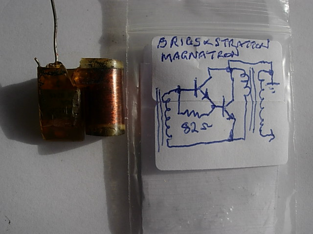
This is a Briggs & Stratton ignition coil that I pulled apart again uses a Darlington transistor to fire the coil.
June 6, 2018 at 2:09 am #77508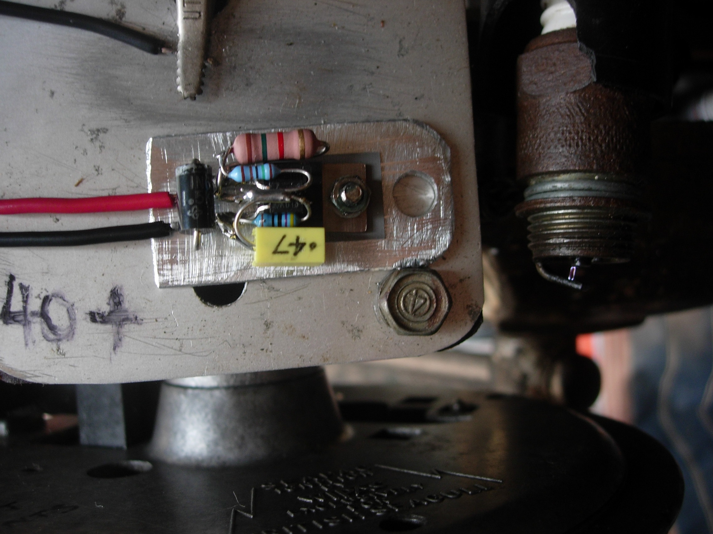
At cranking speed there is a good spark with the home made module.
September 19, 2018 at 10:14 pm #83220I’ve been working on a home-built version of the ‘Brown’ module I’ve rigged on an outboard built from a 1939 Evinrude Midget Racer drive with 1954 J.A.P. 34cc Model ‘O’ attached.
It’s set up with a switch so I can switch from contacts and condenser to electronic and make comparisons immediately. I’m also running it in water to provide a realistic load.
I struggled with getting high speed and low speed running, it would do one but not the other. When I changed the value of C1 it would work better at one end and be worse at the other. There was no single value that would work.
Now I’ve had my timing strobe on the job, I’m shocked to discover that it does not behave as stated. The amount of advance actually reduces as speed increases.
At idle the timing is around 18 degrees BTDC, and it drops to 10 degrees at full throttle. Timing on contacts is 15 degrees at all speeds.I rigged a lash-up with a 10K pot and a 0.47uF capacitor in parallel with C1 so I could add more capacitance at low speed by dialling down the pot to zero, and I used a 0.1uF for C1 to give better running at high speed. This gave good results. Better than running on contacts in both cases.
Now with the pot at zero C1 = 0.47uF+0.1uF, and at idle the timing is around 16 BTDC
with the pot at 10K C1 is pretty much just 0.1uF and in this configuration running at speed the timing is 20 degrees BTDC. That would be a workable configuration, but I still wanted to get to the bottom of it.My thoughts are as follows:
– the reactance of C1 in parallel with R3 changes the voltage ratio of the R2 R3 potential divider. As speed increases the voltage on the base of Q2 is lowered more because increasing dv/dt cause the capacitive reactance to fall.
– Q2 still needs 0.7 volts to turn on,
– so as speed increases the voltage applied to the module has to rise higher to get 0.7 volts at the base of Q2.
We might make the assumption that the peak voltage from the magneto increases as speed increases, but if it increases at a lower rate than the potential divider falls, then the timing will be later not earlier. That’s what I’m finding.I have to repair my Oscilloscope, so it’ll be a few days before I can get some traces and see what the actual voltages and rise times are, but at the moment, I’m looking at dumping C1 altogether and just setting the trigger point by adjusting the values of R2 and R3. Actually I’ll probably replace C1 with a small disc ceramic to decouple any spikes that might cause spurious triggering.
It’s possible that the effect I’m noticing is unique to the Wipac ‘Bantamag’ magneto due it’s relatively high inductance. In which case this work won’t be of much value to anyone else, but I’d welcome comments and suggestions.
September 20, 2018 at 6:27 am #83258I found the Wipac ignition coil on Seagull outboards particularly destructive to these modules. Whereas the Villiers Seagull coil was quite happy with the module. Very interested in what you find.
September 23, 2018 at 8:43 pm #83426Further tests: still basically a ‘Brown’ module with changes..
C1=47pF disc ceramic
R2 is a composite consisting of 100K Pot with a series 2K7 all in parallel with a 3K3. This gives a range of adjustment from 1400 to 3120 ohms without the sporadic noise of a just using a potentiometer on its own (which killed the engine as soon as I moved it).
By the way I’m using a TIP162 for Q1. It’s designed for exactly this kind of job.Results as follows: ( using timing Strobe. ‘Scope pictures are not readable. I’ll try again another time)
R2 at 3210 18 degrees advance
R2 at 2720 22 degrees advance
If R2 is less than 2700 the engine will not run. The adjustment is not linear, and this part of the range is more sensitive, so there’s a bit of leeway here. Mark it down for further testing.These timings remain the same at all speeds. This is a significant point. We expect that peak coil voltage increases with speed, and hence the trigger point should occur earlier.
From the above we can get the trigger voltage:
With R2=3210 the Pot Div ratio is 0.2427 and the voltage required to trigger is 2.884V. This occurs at 18 degrees BTDC
With R2=2720 the Pot Div ratio is 0.2688 and the voltage required to trigger is 2.604V. This occurs at 22 degrees BTDCWe don’t know the coil characteristic (bad ‘scope), but we can deduce that:
– It is only around 2.6 volts at 23 degrees BTDC, the point at which the module ceases to operate as the trigger point voltage is reduced.
– Any earlier than this point it seems there is not enough energy in the coil to create a spark when the module triggers.From this I have learned:
I can make the module timing adjustable up to a maximum advance of 22 degrees with this magneto.
This engine improves it’s mid and full throttle performance with more advance than the present static timing of 15 degrees.
The engine will chug along at idle with the timing at 22 degrees advance, but it is much smoother with it at 15 degrees.
If I want any more advance than 22 degrees, I’ll need to move the magneto plate, the module can’t be pushed any further.
The magneto plate is already at maximum advance adjustment, plus the holes are elongated by an extra 2mm to get it where it is.So my options are:
Stick with what I’ve got and just tidy it all up. Retain the contacts and the Normal/Electronic changeover switch as a fallback system.
Fix the module timing at 22 degrees, and just switch to contacts when idling.
Or
Completely rebuild the magneto plate mounting to allow further adjustment. This isn’t as difficult as it might sound. The plate is quite flat on the underside and mounts on two raised posts, so the posts could be machined lower and an intermediate rotator plate fitted to provide a mechanical advance adjustment like my old Johnson 10. If I went down this route, then I could lose the contacts and go electronic.I’ll still continue with the ‘scope and try to get some usuable pictures, and I’ll test the effect of a small inductor in series with R3 to see if it will provide automatic advance.
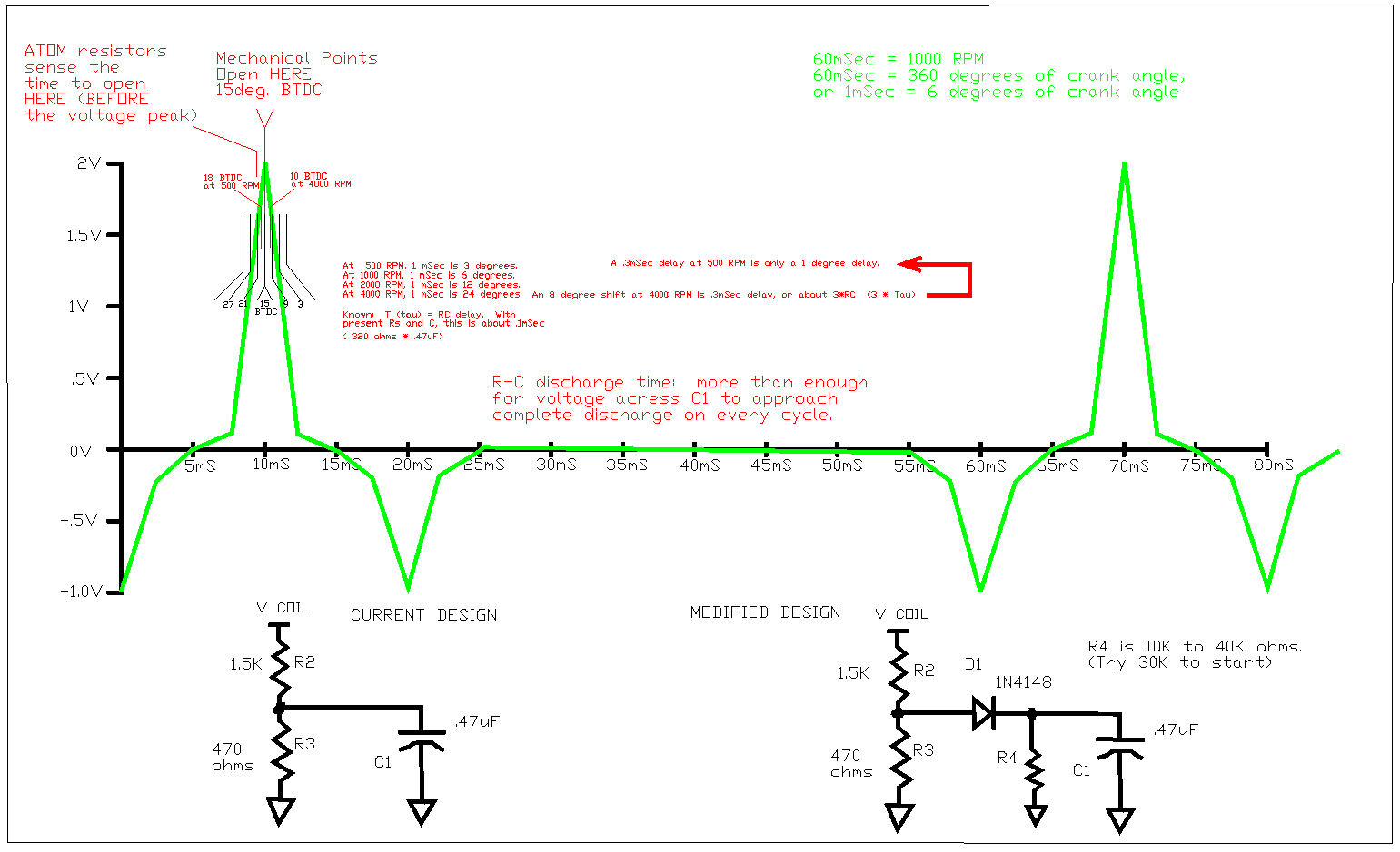
September 26, 2018 at 4:45 am #83542About the timing change in the ATOM modules at different RPMs…….this is completely expected. I’ll try to explain.
In a conventional (magneto / breaker points) ignition system, the spark is timed with mechanical points being moved
by the lobe on a cam. The "break point" is the exact same location, no matter what the RPM (assuming you are
NOT rotating the distributor plate). The points open up when current through the primary of the spark coil is at
maximum. The position of the magnets in the flywheel, and the "pickup coil" and the position of the points are
all mechanically arranged for the points to open when coil current is at maximum. This changes very little with
RPM.In contrast, the ATOM module is triggered by VOLTAGE ACROSS THE POWER DARLINGTON. This voltage across the
power darlington is roughly proportional to the current going through it……..but, the ATOM module doesn’t "know"
when the current is at maximum……….so, they GUESS, by setting the "trip point" slightly early at lower RPM. (maybe
2 or 3 degrees early at 500 RPM.) The resistor pair R2 and R3 form a voltage divider, that sets this initial voltage
"trip point".Capacitor C1, in combination with the resistance of R2 and R3 in parallel, forms a low-pass simple R-C filter.
(Time delay T, or "tau", is simply R*C). As the parallel combination of R2 and R3 is about 320 ohms, against a .47uF capacitor,
this will give you a "tau" delay of about .1 millisecond…..or about a 2 degree timing DELAY at 500 RPM.
Please note that this time delay is a FIXED VALUE in TIME. (This is about 3 * TAU delay, or .3 mSec).SO……the R2/R3 split was probably setting the "trip point" at about 20 degrees before top dead center.
The R2/R3 * C1 "filter delay" sets that back about 2 degrees, so you see the actual "firing point" at about 18
degrees Before Top Dead Center (as compared to the 15 degrees you saw with points). This isn’t enough of
a timing error for most people to notice.Now, at higher RPM (say, 4000 RPM)….things change dramatically. Specifically:
1) The voltage created by the higher RPM is about double or more what you see at lower RPM…..
so the voltage-based "trip point" sensed by R2/R3 is a bit earlier (maybe a degree or two.)HOWEVER —
2) The RC timing delay is FIXED………and what caused only a 1 or 2 degree timing delay at 500 RPM,
has 8 times that effect at 4000 RPM. ….8 to 10 degrees of additional delay.So, yes, while the voltage trip point is SENSED a few degrees earlier at higher RPM, the fixed timing
delay of about .3 milliseconds causes the final "firing point" to be about 8 degrees LATER than you see
at only 500 RPM.This explains why (with the ATOM) you see 18 degrees BTDC at 500 RPM, and only 10 degrees BTDC at 4000 RPM.
You get an additional 8 degrees of delay at the higher RPM…..due entirely to the R-C timing delay of the
R-C "filter" formed by R2, R3 and C1. (This delay also has a filter function, to prevent false triggering
and erratic timing, so you really can’t eliminate C1.)SO………compared to the "points" that give you a fixed 15 degrees BTDC firing point at any RPM, the ATOM
fires about 3 degrees too early at idle, and about 5 degrees too late at higher RPM. MOST USERS of
chain saws, lawn mowers (etc) would never notice this. And, frankly, most outboard motor people that
used the ATOM didn’t have oscilloscopes, so they never really noticed the timing discrepancies either.
The ATOM was "good enough" for most people………..except people who really want good performance.See the attached timing diagram (attached to this e-mail message)
See: Atom_RC_Delay.jpgNow, this R-C filter timing delay is fixed, (in the current design). You CAN compensate for this by having
the capacitor hold a bit of voltage with increasing RPM, and you can probably get several degrees of timing
adjustment closer to the 15 degrees desired by doing this.Look at the schematics at the bottom of my drawing. The schematic to the left is the "stock" ATOM
design. Resistors R2 and R3, along with C1, form a RC low pass filter (and fixed timing delay). By
putting a diode in series with the line going to C1, and a SEPARATE "discharge resistor" (R4), you can
have C1 pump up a voltage proportional to the RPM, which will adjust the timing earlier. R4 controls
the rate of discharge (and hence, the voltage adjustment). R4 should be somewhere between 10K and
40K ohms……..( I don’t have the time to work out the details here.)Also, the .7V drop across the small signal diode will screw with the initial "trip point", so R2 will probably
have to be adjusted lower to compensate for that diode drop.*********** Anyhow, the ATOM was "good enough" for most people. If you really want to design a replacement
that will work extremely well across all RPM, and across many different types of spark coils, ….that’s going to
take some serious effort.–Bill Mohat AOMCI, Cleveland, Western Reserve Chapter
Attachments:
***********************************************************************
Bill Mohat MS/CIS, BSEET, CCNA"You can avoid reality, but you cannot avoid the consequences of avoiding reality." --Ayn Rand **********************************************
-
AuthorPosts
- You must be logged in to reply to this topic.