Home › Forum › Ask A Member › Speeditwin Magneto
- This topic has 26 replies, 10 voices, and was last updated 5 years, 10 months ago by
 Buccaneer.
-
AuthorPosts
-
June 20, 2018 at 11:37 pm #78234
Perhaps everyone needs to refocus on the original question. Buccanneer asked the question about the secondary leads going into the bakelite insulators. Here’s my take:—I like it! The secondary leads coming off the coil are soft and don’t put any stress on the coil’s tab (connection). The insulators on the inside have a female receiver similar to that of a conventional distributor. The wires coming from the coil should have ends soldered on them that are expanded similar to what you see on plug wires that fit into the distributor but in a miniature version. The system is designed such that the plug (coil) end when pushed into the bakelite receiver has a stress fit, and it is good and solid. When you remove that secondary wire from the insulator you should see a screw down inside. That screw is what holds the spark plug wire firmly. When installing new plug wires, I solder them, insert them into the underside of the bakelite fitting and tighten the screw. They are then held firmly in place. The solder helps to keep the wire firm when the screw is tightened.
The reason I like the design is because you can change spark plug wires without damaging the coil. If you are going to use the described grommet, you’ll have to solder the wires to the coil and risk damaging the secondary connection, plus any strain put on the plug wires puts strain on that valuable, original coil.
George
June 20, 2018 at 11:55 pm #78236George, I read your reply too late, although I did reuse the bakelite
connectors. I trimmed the insulation on the plug wires back enough
where the bare wire stuck up above the bakelite towers far
enough to solder on the braided wire leads from the coil.
There were no screws inside the towers, but rather the
secondaries wires from the coils were just butted up against
the plug wires inside the towers.
If you have photos of the correct way to connect the plug wires,
I’ll try that next time! I’m not sure I’m visualizing what you say.I never did get a good reading on the secondaries on my ohm meter,
but I had a nice steady spark on the Stevens tester at about 2.2 to 2.3 amps.The Speeditwin mag plate I acquired is missing the advance lever.
I believe this mag is from the 1940’s. Did they have a "kill" button
in the lever? I can make a lever, as the whole setup isn’t going
to be correct for my Speedster anyway, but not sure about
the kill button.
Thanks.
Attachments:
Prepare to be boarded!
June 21, 2018 at 1:17 am #78243That came out nice.
June 21, 2018 at 2:09 am #78247Buc,
What did you use to clean the junk off the coil? Like Tub’s said, that turned out nice.
June 21, 2018 at 2:19 am #78248quote david bartlett:Buc,What did you use to clean the junk off the coil? Like Tub’s said, that turned out nice.
Acetone and rag took most black stuff off, putty knife in areas.
Prepare to be boarded!
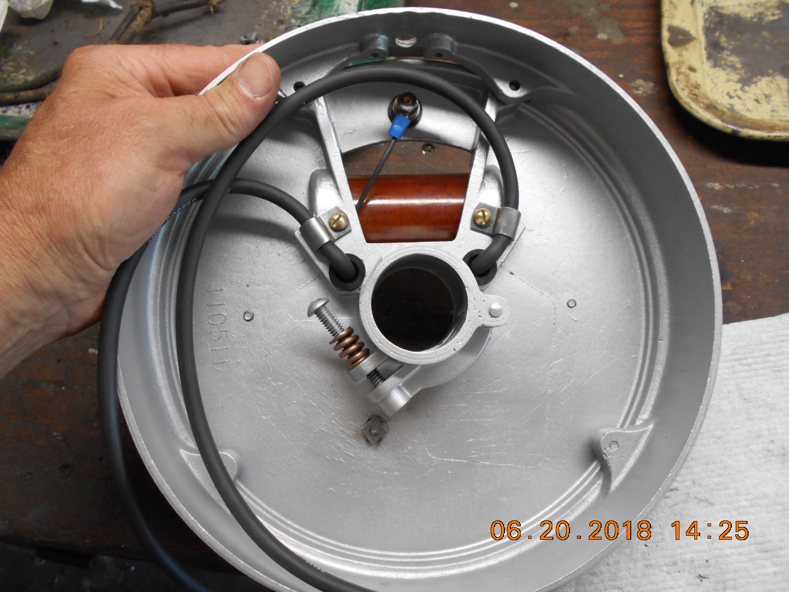
June 21, 2018 at 4:07 am #78255Yes. the handle has a button with a rod on the end that shorts the points via the insolarted brass bolt you show in your picture of the bottom of the magneto base. . . 🙂

 June 21, 2018 at 12:27 pm #78260
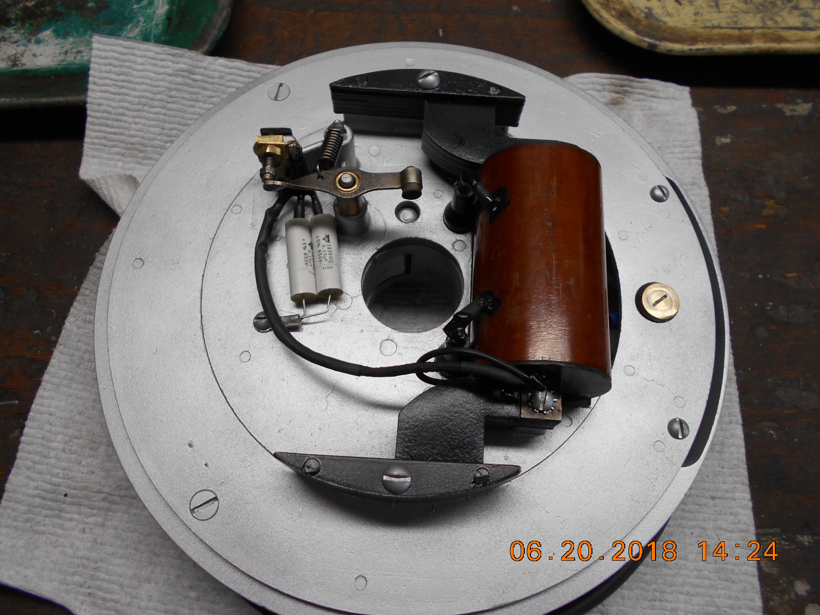
Looks great from here. Just curious, why 2 capacitors? I’m electrically challenged so capacitors still baffle me.
June 21, 2018 at 5:31 pm #78264Wired in parallel like that doubles the capacitance, wired in series doubles the voltage. So if you needed a 0.3 µƒd capacitor you could use two 0.15 µƒd capacitors in parallel to do the job. The 170002 capacitor the Speeditwin uses is specified to be from 0.27 to 0.36 µƒd. . . 😉
June 21, 2018 at 6:20 pm #78265quote SquierKA39:Looks great from here. Just curious, why 2 capacitors? I’m electrically challenged so capacitors still baffle me.I used two 1.5 uf caps. I put the ends with the same markings together,
but I’m not sure if it maters?Prepare to be boarded!
June 22, 2018 at 1:08 am #78272I made up a handle for the mag plate this morning. Looks like
something a plumber would come up with, which I’m not. 😯
Attachments:
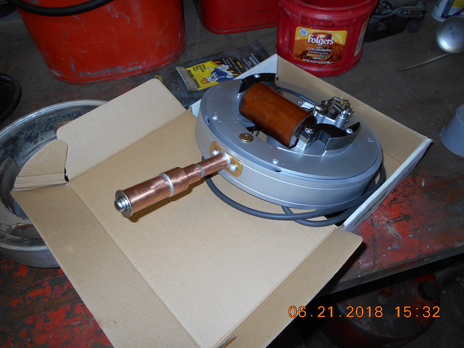
Prepare to be boarded!
-
AuthorPosts
- You must be logged in to reply to this topic.